
Strobe Light Circuit with Timing PCB
This strobe light circuit is designed for versatility in flashing rates, making it suitable for various applications such as photography, signaling, or decorative lighting effects. The use of a flash tube, as opposed to standard LED or incandescent bulbs, allows for a more intense burst of light, which is particularly useful in situations where high brightness is required for a short duration.
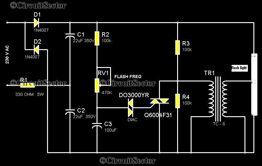
The circuit begins with an AC power source, which is first rectified by the 1N4007 diodes. These diodes are essential for converting the alternating current (AC) into direct current (DC), ensuring that the subsequent components receive a stable voltage. The 22/350V capacitors play a critical role in this process by smoothing out the rectified voltage and storing energy, which is later released to trigger the flash tube.
The adjustable potentiometer is a key feature of this circuit, allowing users to fine-tune the flashing rate. By varying the resistance, the user can control the voltage that charges the capacitors, which directly influences the time it takes for the capacitors to charge and discharge. A lower resistance results in a faster charge and discharge cycle, leading to a quicker flash rate, while a higher resistance slows this process down.
The triac serves as a switch that is triggered by the voltage from the capacitors. Once activated, it allows current to flow to the output transformer. This transformer steps up the voltage to a level sufficient to ignite the flash tube. The flash tube then emits a bright, short-duration pulse of light, ideal for capturing high-speed events or creating visual effects.
In summary, this strobe light circuit effectively combines components to create a flexible and powerful lighting solution, with an emphasis on user control and rapid response times. The integration of the flash tube enhances its functionality, making it a valuable tool for various lighting applications.Here is a strobe light circuit which has an option to set the flashing rate. Unlike other circuits here we use a Flash tube that usually use in flash cameras. In ordinary cameras, the flash may be work only after ten or twenty seconds. But in this circuit we can adjust flashing time by adjusting the potentiometer provided in the circuit. 1N4007 di odes and the 22/350V capacitors do the job of converting the input AC voltage into DC. This gives the triggering voltage to triac. The potentiometer adjust the voltage through it and this result change in the charging and discharging time of 22/350V capacitors. The output of the triac is connected to the output transformer which enlarges the voltage to drive flash tube.
🔗 External reference
Related Circuits
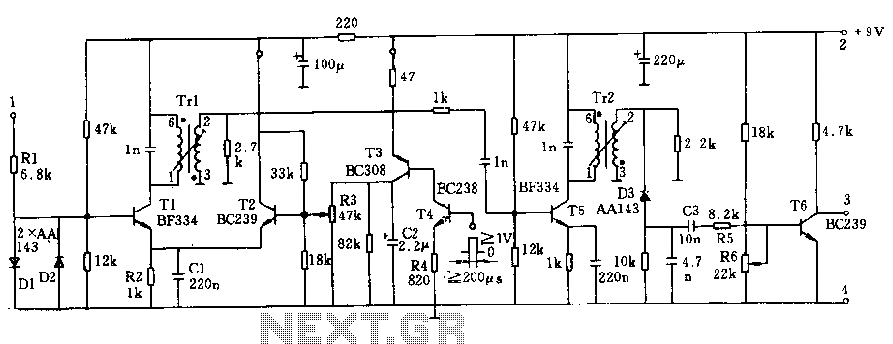
The circuit operates at a voltage of 9V with a current consumption of only 5mA. It allows for frequency adjustment within the range of 150 to 180 kHz, featuring a bandwidth of approximately 20 kHz. This configuration ensures that...

The utility vehicle anti-theft alarm circuit consists primarily of two main components essential for its operation. The security circuit is activated when the vehicle owner departs from the vehicle, utilizing an anti-theft switch (S B) to engage the alarm...

Merry Company (Micrel Inc.) introduced the industry's smallest and most powerful LED driver, the MIC2298, which is widely used in portable electronic devices. The device is a 7W efficient boost DC/DC converter, packaged in a compact 3mm x 3mm...
The Accu charger circuit is straightforward and simple to construct, requiring no more than ten components. In addition to its ease of assembly, this charger circuit is also cost-effective and highly efficient. The circuit requires a power supply from...
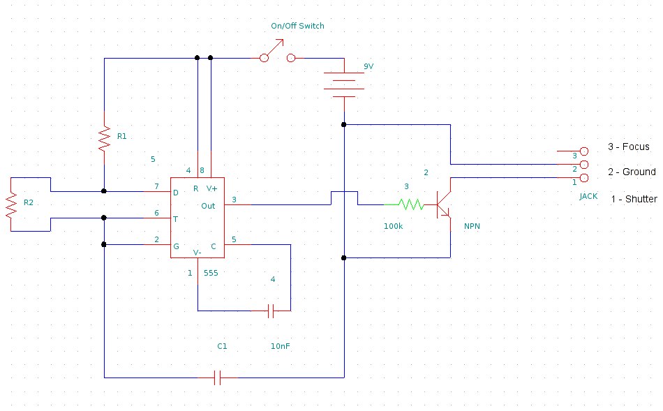
This document provides information on constructing a DIY time-lapse circuit that enables a camera to automatically capture images at specified time intervals. These images can then be compiled to create a time-lapse film. The circuit utilizes a 2.5 mm...

CMOS interface circuit with PMOS cross-coupled PMOS integrated circuit featuring high input impedance, where the input current can be ignored. The CMOS and PMOS interface circuit is illustrated in the accompanying figure. The CMOS interface circuit utilizing PMOS cross-coupled configurations...