
Tic Tac Tunes Circuit Diagram

In this circuit design, the primary power source is a compact 6V battery, which is advantageous in applications where space constraints are significant. To achieve the desired operating voltage of 4.8V for the PicAxe microcontroller, two silicon diodes, labeled D1 and D2, are used in series. Each diode typically has a forward voltage drop of approximately 0.6V to 0.7V, thus the combined drop across both diodes results in a total reduction of about 1.2V from the initial 6V supply.
The PicAxe chip, a popular microcontroller for educational and hobbyist projects, operates efficiently at 4.8V. This voltage level is crucial for ensuring the chip functions correctly without risking damage from overvoltage. The circuit may also include additional passive components, such as capacitors for smoothing and filtering purposes, to stabilize the voltage supply to the microcontroller and mitigate any noise.
It is important to consider the current requirements of the PicAxe chip and ensure that the diodes selected can handle the load without overheating or exceeding their current ratings. The choice of diodes should also account for their reverse voltage ratings to prevent breakdown in case of reverse polarity connections.
In summary, this circuit effectively utilizes a small 6V battery and employs two diodes to achieve a regulated 4.8V supply for the PicAxe microcontroller, making it suitable for compact electronic projects where space is limited.As space is at a premium here, I`m using a small 6V battery and dropping the voltage down by 1.2V to 4.8V with the diodes D1 and D2. The PicAxe chip.. 🔗 External reference
Related Circuits

A circuit diagram illustrating the reliability of crystal startup, with power consumption significantly lower than the maximum allowed for the crystal. The transistor Q1 can be one of the following: 2N918, 2N3564, 2N5770, BF180, or BF200. The inductor L1...

The circuit features an AC input from VDI, which is converted to pulsating DC power using a VD4 full-wave bridge rectifier to power four lights. Resistors R1 and R2, along with diode VD5, form a simple circuit, while VD6...
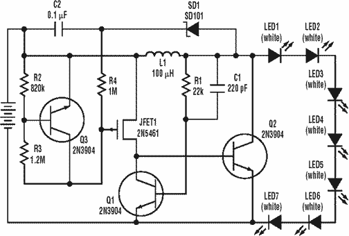
A low power, long-life LED flashlight circuit. Electronic Design proposed a simple circuit to resolve this in a recent article. The front end of their circuit draws less than a milliamp of extra current. The described LED flashlight circuit is...

The circuit generates a controlled pulse signal. When a high pulse signal is applied to the input terminal O (start), the output pulse signal is activated. Conversely, when a low signal is received at the input terminal O (stop),...
T1 and T2 in the circuit form the inherent oscillator, while T3 serves as the output stage. The network consists of a high-pass filter (C3, C4, R6, and R7) and a low-pass filter. The output from this network is...
This is a simple mains power failure alarm circuit that activates an alarm when the mains supply is lost. Unlike many similar circuits, this design does not require a backup power source, such as a battery, to operate the...