
15-65MHz circuit diagram of the third harmonic

The circuit diagram focuses on enhancing the startup reliability of a crystal oscillator while maintaining low power consumption. The selection of transistors such as the 2N918, 2N3564, 2N5770, BF180, or BF200 allows for flexibility in performance characteristics, ensuring that the circuit can be tailored to specific application requirements.
The resonator's specifications indicate that it operates efficiently at two distinct frequency ranges, with the 22pF capacitance ensuring that the oscillator maintains stability across these frequencies. The inductor L1 plays a crucial role in tuning the oscillator circuit, allowing it to resonate at the desired frequencies of either 15-30MHz or 30-65MHz, depending on the selected inductance.
This design is particularly advantageous for applications requiring precise frequency generation with minimal power draw, making it suitable for battery-operated devices or energy-efficient systems. The combination of the chosen components facilitates a reliable oscillator that can maintain performance under varying operational conditions, thereby enhancing overall circuit reliability and efficiency.A circuit diagram of the crystal startup reliability, power consumption is much lower than the crystal maximum allowed. Q1 is 2N918,2N3564,2N5770, BF180 or BF200. L1 frequency crystal resonator is 22pF (15-30MHz, 1 H or 30-65MHz, 0.5 H). As good stability and the fundamental frequency oscillator.
Related Circuits

This circuit is a small digital roulette. It consists of an oscillator IC1, a counter IC2, and transistors Q1-7 that drive the common cathode display DSP1. The power supply typically comes from a 9V battery, but it can also...

The AM transmitter circuit consists of an audio amplifier and an RF oscillator. The oscillator is constructed around transistor Q1 and its associated components. The tank circuit, which includes inductor L1 and variable capacitor VC1, is tunable from approximately...

This document describes a specific module utilizing the CF8865 switching power supply circuit, which employs the integrated control module CF8865. In the figure, transistors VT4 and VTs are controlled by the excitation transformer Tz. The output is processed through...

When testing a circuit, a variable voltage source with overvoltage shutdown capabilities is highly beneficial. In this circuit, resistor R1 is adjusted to a value 1 to 2 volts below the eventual shutdown threshold. Resistor R2 is responsible for...

The DIY Electronic Siren circuit described here can produce three distinct US-style siren sounds: DIY police, DIY ambulance, and fire engine. The desired sound can be selected using switch S1. This circuit is suitable for use in toys (such...
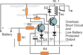
The battery voltage must pass through resistor R1 before reaching the output load. As a result, the current flowing through R1 is proportionately transformed into a voltage across it. When the battery voltage drops below a certain threshold, the...