
Touch Switch
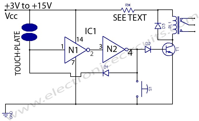
The touch switch circuit operates by utilizing the capacitive touch sensing principle, which allows the user to activate the switch without the need for physical contact. The core component, a CMOS inverter, serves as the primary switching element. When a finger approaches the touch plate, it alters the capacitance at the input of the inverter, causing a change in its output state.
The output of the CMOS inverter is connected to a buffer transistor, which acts as an interface between the low-power CMOS output and the higher current requirements of the load (LEDs, relays, etc.). The buffer transistor is typically configured in a common-emitter arrangement, allowing it to amplify the current from the inverter output to drive the load effectively.
Additional components may include resistors for biasing and pull-down configurations, ensuring stable operation and preventing false triggering. A capacitor can be added in parallel with the touch plate to filter out noise and provide debounce functionality, enhancing the reliability of the touch switch.
The circuit is powered by a DC supply, with considerations for the voltage ratings of the components used. Proper selection of the transistor based on the load requirements is essential for optimal performance. The design is versatile and can be adapted for various applications by changing the load or modifying the touch sensitivity through component values.Here is a touch switch that can be used to drive LEDs, relays etc through a buffer transistor stage. It may be built around any CMOS inverter chip 🔗 External reference
Related Circuits
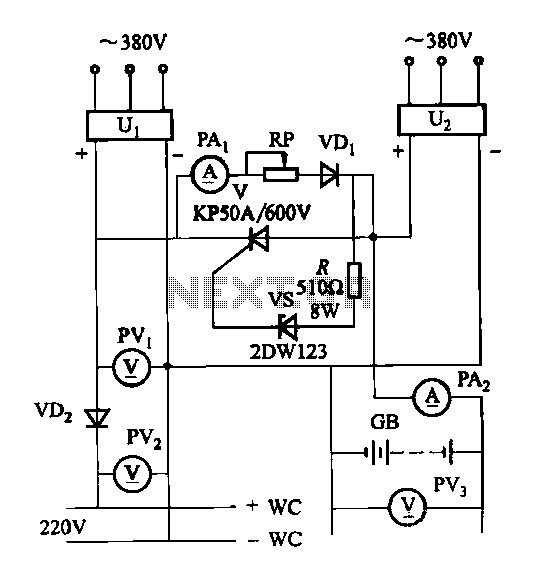
The DC panel battery is commonly utilized in power plants and substations within DC systems. To enhance the safety and reliability of the current system, an uninterrupted power supply switching circuit may be implemented. This circuit includes components such...
The switch control system utilizes sensors to inform the microcontroller of the trains' positions on the layout. This ensures that only one train occupies the main line at any given time and that switches are correctly set for the...
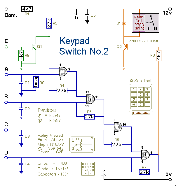
This is a simplified version of the 4-Digit Keypad Controlled Switch. The design has been modified to reduce circuit complexity and the number of components required. Consequently, the code is somewhat less secure, but it should be sufficient for...
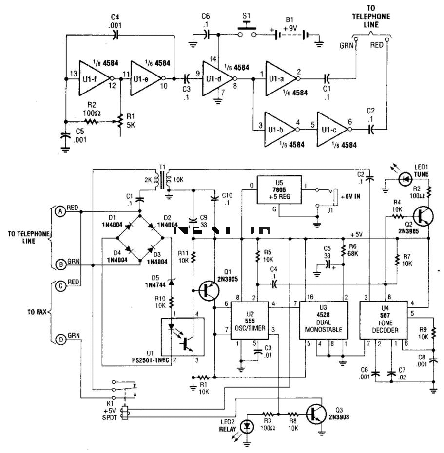
This system uses a transmitter operating at approximately 100 kHz to control a remote receiver. A line splitter can connect the transmitter to the active telephone line. The transmitter is a CMOS oscillator equipped with output buffer stages to...
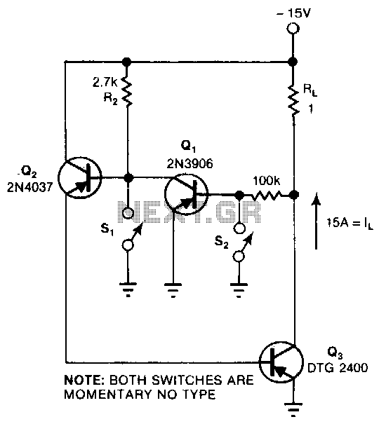
This circuit provides the turn-on characteristics of a Silicon Controlled Rectifier (SCR) but allows for easy turn-off. The switch consists of three transistors with decreasing current ratings: Q3 has a high current rating, while Q2 has a medium rating....
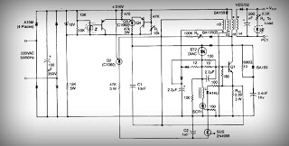
This is a low voltage, high-current output switching DC power supply with an input of 220 volts AC. In this circuit, an ST2 DIAC relaxation oscillator, Q3, C1, and the DIAC initiate conduction of the output switching transistor Q1....