
keypad controlled switch

The 4-Digit Keypad Controlled Switch is an electronic circuit that allows users to manage power to a device through a keypad interface. The design typically incorporates a 4x4 matrix keypad, a microcontroller, and a relay module. The microcontroller interprets the key presses from the keypad, enabling users to enter a 4-digit code to activate or deactivate the switch.
In this simplified version, the circuit utilizes fewer components, which may include a basic microcontroller such as an ATmega series or a PIC microcontroller. The microcontroller is programmed to recognize the specific sequence of digits entered via the keypad. The relay module, which can be a single-channel relay, is used to control the power to the connected load.
When the correct 4-digit code is entered, the microcontroller sends a signal to the relay, activating it and allowing current to flow to the load. If an incorrect code is entered, the microcontroller can be programmed to provide feedback, such as an LED indicator or a buzzer, to alert the user of the failed attempt.
Although the simplified design results in reduced security, it is suitable for applications where high security is not a critical concern. This design can be effectively used in home automation systems, simple access control systems, or for controlling non-critical devices.
Overall, the 4-Digit Keypad Controlled Switch serves as a practical solution for managing electronic devices with a user-friendly interface while maintaining a balance between complexity and functionality.This is a simplified version of the 4-Digit Keypad Controlled Switch. I have modified the design to reduce the complexity of the circuit - and the number of components required. As a result - the code is somewhat less secure. However, there should be lots of situations where it will still be adequate.. 🔗 External reference
Related Circuits
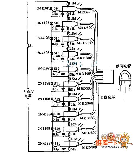
Light emitted by a Xenon flash tube is transmitted to the phototransistor MRD300 through an optical fiber. The sensitive current is amplified to trigger a series of thyristors simultaneously. Consequently, a high voltage of 6000V is applied to loader...
As with the Electronic sel. 8 we also have here a circuit with a choice of 8 different sources. The difference is that only two of the switches are used and the movement of commands is Up-Down in series....
This circuit can be used for multiple cameras with one monitor. The circuit can be operated manually or automatically. The described circuit functions as a video switching system, enabling the connection of multiple camera inputs to a single monitor output....

Q1 senses infrared radiation from heat sources, which causes U1 to switch on, activating optocoupler U1 and triggering TRIAC TR1. This controls a fan. The TRIAC can be sourced from Radio Shack or a 200-V, 6-A unit (C106B) can...
This circuit was adapted from the Toggle Switch Debounced Pushbutton by John Lundgren. It is useful where the load needs to be switched on from one location and switched off from another. Any number of momentary (N/O) switches or...
A daily switching power supply primarily provides direct current (DC) power to electronic devices. The required DC voltage for electronic devices typically ranges from several volts to over ten volts, while the input voltage from the mains supply is...