
VHF antenna amplifier circuit diagram

This RF antenna amplifier circuit is optimized for enhancing signal reception in the VHF frequency range, making it suitable for applications in both radio and television. The design incorporates a gain of 22 dB, which significantly boosts the incoming signal strength while maintaining low noise levels, crucial for clear audio and video output. The low noise figure of under 1.6 dB ensures minimal signal degradation, making this amplifier particularly effective in environments with weak signals.
The circuit utilizes two inductors, L1 and L2, which play a vital role in tuning and filtering the frequencies of interest. The L1 coil, rated at 6 µH, can be replaced with other inductors within the range of 5.6 to 6.8 µH, allowing for some flexibility in component selection based on availability and specific tuning requirements. The L2 coil, constructed as an air core with 5-6 turns, is designed to optimize the amplifier's performance by reducing losses associated with core materials. The dimensions of this coil are critical, with a length of 10 mm and a diameter of 5 mm, ensuring efficient electromagnetic coupling.
When assembling the circuit, it is recommended to use 0.25 mm copper wire for the L2 coil to ensure adequate conductivity and minimal resistance. The PCB layout should be compact and designed to minimize parasitic capacitance and inductance, which could affect the amplifier's performance. Additionally, placing the PCB close to the antenna within a metallic enclosure helps shield the circuit from external interference, enhancing overall signal integrity.
Powering the circuit requires a stable 12-volt DC source, which can be conveniently provided by a 12-volt battery. The low current consumption of under 10 mA allows for prolonged operation without significant energy depletion, making it suitable for portable applications. This design is ideal for hobbyists and professionals looking to improve VHF signal reception in various environments, ensuring reliable performance in both urban and rural settings.This RF antenna amplifier can be used for high frequency and VHF band ( for radio and TV) and will provide a 22 dB gain. This RF antenna amplifier electronic project has a very low noise, under 1. 6dB. L1 coil has a 6uH value, but can be used any coil for high frequency ( with a value between 5. 6 to 6. 8 u H). L2 coil is an air core type coil a nd it has 5-6 turns (10mm long and 5 mm diameter). For L2 coil can be used a 0. 25 mm Cuem wire. The pcb of this circuit must be placed near the antenna, in a small metallic box. This VHF antenna circuit must be powered from a 12 volts DC power supply circuit, you can use a 12 volt battery, because the current consumption of this circuit is very low under 10mA. 🔗 External reference
Related Circuits
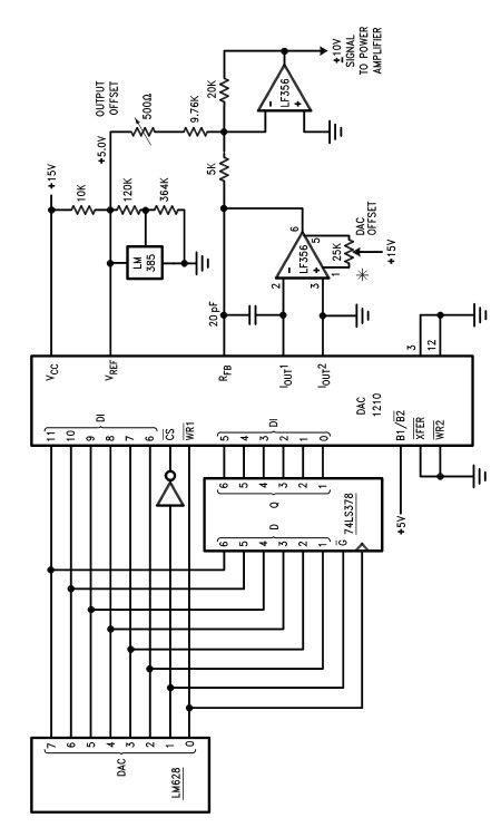
The LM628 and LM629 dedicated motion-control processors can be utilized to design various applications involving DC and brushless DC servo motors, as well as other servomechanisms. The power path of this electronic project, which functions as a motor driver,...
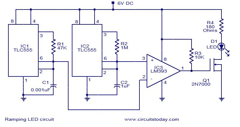
In this circuit, the intensity of the LED varies in a ramping fashion. The circuit comprises three integrated circuits: two 555 timer ICs and one LM393 operational amplifier. IC1 and IC2 are configured as oscillators to generate frequencies of...
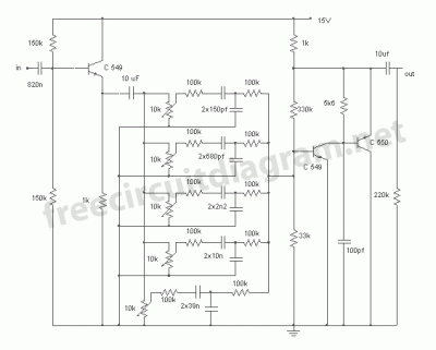
This circuit is a five-channel equalizer designed for a single line channel. The working principle of this series involves a series of frequency filters with a center frequency of 10 Hz. The five-channel equalizer circuit is structured to manipulate audio...
This DC to DC converter increases a DC voltage to nearly double its original value and is useful for elevating the output voltage of solar batteries to the required level. The DC to DC converter operates on the principle of...
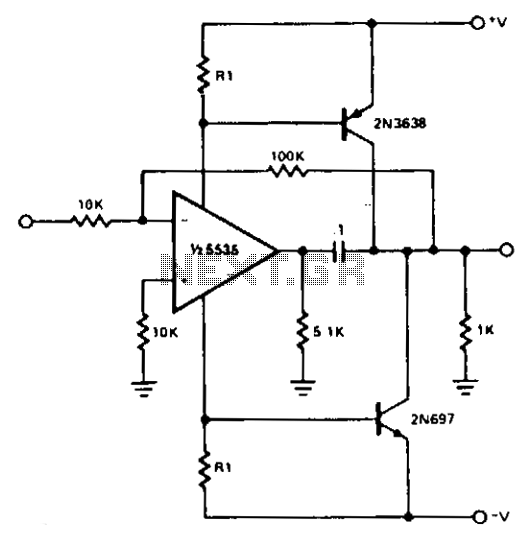
For most applications, the power provided by operational amplifiers (op amps) is adequate. However, there are instances where a greater power handling capability is required. A straightforward power booster that can drive moderate loads utilizes the NE5535 device. Other...
Even though the power was off, there was AC present at the handle plug, and a short circuit occurred. Upon disassembly, a blown transistor was discovered. An attempt was made to fix the issue, but after one month and...