
analog How to analyze this diode circuit
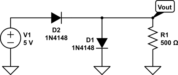
In the described circuit, the use of two diodes suggests a configuration that may be intended for rectification or signal clipping. The inclusion of series resistors is critical to limit the current flowing through the diodes, thereby preventing potential damage due to excessive current. Diodes, when subjected to currents beyond their rated specifications, can fail, resulting in one or both diodes becoming non-functional. The term "Smoke Emitting Diode" humorously refers to a diode that has been damaged to the point of emitting smoke, indicating a catastrophic failure.
To ensure proper functionality, it is essential to verify the orientation of the diodes in the schematic. Diodes are polarized components, and incorrect placement can lead to reverse bias conditions that may damage the diode or alter circuit behavior. If D1 is incorrectly oriented, it is advisable to analyze the circuit under the assumption that D1 has failed. This analysis should include recalculating the expected currents and voltages throughout the circuit to understand the implications of the failure.
Additionally, it is important to consider the assumptions made during the simplification of the circuit model. The constant voltage drop model, which assumes a fixed voltage drop across the diodes, may not accurately represent real-world behavior under varying current conditions. This discrepancy can lead to significant errors in circuit analysis, necessitating a more detailed examination of the diode characteristics and the overall circuit behavior.
In summary, the circuit design involving diodes requires careful consideration of component orientation, current limiting strategies, and the validity of assumptions made during analysis. Properly addressing these factors will enhance circuit reliability and performance, while also providing valuable insights into the behavior of the system under various conditions.The two diodes will be fried. You`ll want some series resistors for them. If the simulation runs, the current through the diodes will be huge. jippie Apr 30 `13 at 9:40 @jippie Both diodes need not be fried :-) One will become a SED (Smoke Emitting Diode), then we can always analyze for the remaining one! Anindo Ghosh Apr 30 `13 at 9:42 If you drew the schematic yourself, I`d double check the reference to make sure you got the D1 polarity correct. In this situation, I would probably make a note of the problem with the circuit as drawn, possibly solve it assuming D1 died, and then additionally solve it assuming D1 was reversed (which was likely the intention).
darron Apr 30 `13 at 15:26 When you encounter a situation like this, you should realize that some assumption you`ve made when simplifying isn`t valid. In this case, it`s the assumptions of the constant voltage drop model that are being violated. DrFriedParts Apr 30 `13 at 15:50 🔗 External reference
Related Circuits
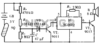
The circuit operates in such a way that when the patient is typically in an upright position, the SQ mercury switch is turned off, resulting in the alarm circuit being inactive. When the patient lies down, the SQ switch...
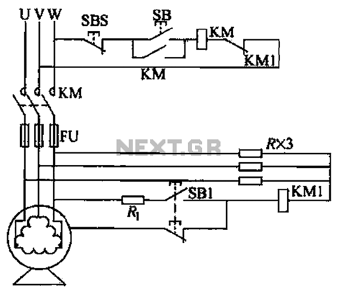
A voltage leakage protection circuit utilizing a resistive element as an auxiliary neutral point is illustrated in the accompanying figure. When selecting the resistance, it is essential to consider both the resistance value and power consistency. The described voltage leakage...
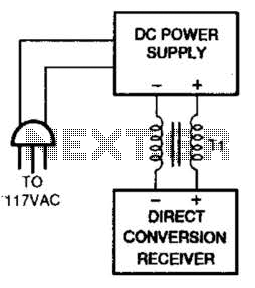
One solution for AC power line hum and ripple, which is caused by leakage current, is to utilize a well-regulated and filtered 9 to 18 VDC power supply that incorporates a balancing choke (Tl in this illustration) between the...
This is a solar tracking circuit designed to harness power from sunlight. The circuit operates optimally by maximizing sunlight exposure to generate electricity. The solar tracking circuit utilizes a combination of photovoltaic (PV) cells, sensors, and a microcontroller to adjust...
When the doorbell switch K1 is pressed, the doorbell rings and LED D3 lights up. If there is no one to answer the door, guests will leave, but D3 remains illuminated, indicating that visitors have arrived. The circuit includes...
This circuit is a simple series tone control circuit utilizing the OP-Amp LM301A. The JFET 2N3684 provides high input impedance and low noise characteristics for the feedback buffer in the op-amp-based tone control. The tone control circuit described employs an...