
atmega

Arduino, an AVR-based prototyping board, emphasizes ease of use and includes breakout headers for input/output pins and power. It also incorporates a USB interface utilizing the FT232RL chip, which enables RS232 serial communication through a USB device, thereby negating the need for a separate AVR programmer. The Arduino project provides an Integrated Development Environment (IDE) for writing AVR code in a C/C++-derived language called Wiring. This IDE includes various libraries and a convenient function framework. The Arduino bootloader will flash Pin 19 (PB5) twice at a 500 ms interval during boot-up, with a low-power LED designated for this purpose or for monitoring the status of custom software. A 470-ohm resistor should be placed in series with the LED.
ATmega chips programmed via the Arduino will function as stand-alone microcontrollers. However, to utilize a new ATmega with the Arduino, it is necessary to write the Arduino bootloader onto the ATmega chip, achievable with AVRDUDE, UISP, or AVR Studio. ATmega chips utilizing the Arduino bootloader will experience a 5-second startup delay during which the bootloader listens for serial data from the Arduino programming environment. If the chip blinks the LED on Pin 13 but does not execute the user code, placing a 10,000-ohm resistor between Pin 2 and Pin 3 is advised, as the bootloader may erroneously interpret noise on these pins as data. Port C connects to the TWI (2-Wire or I²C) module and provides six ADC inputs via the A/D Converter module. It consists of seven I/O pins and supports pin change interrupts. The analog inputs are located on pins PC0 through PC5.
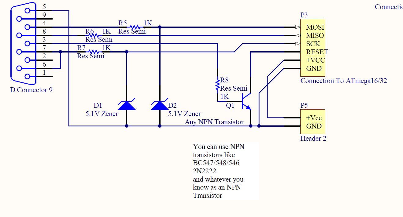
The described system illustrates a typical workflow for programming AVR microcontrollers, emphasizing the integration of hardware and software components. The use of an ISP allows for direct programming of the microcontroller, which is essential for embedded systems development. The Arduino platform serves as a versatile tool for rapid prototyping, enabling users to develop and test applications efficiently. The inclusion of an IDE with libraries enhances the development experience, allowing for easier implementation of complex functionalities. The bootloader mechanism provides a convenient method for uploading new code to the microcontroller without requiring a dedicated programmer after the initial setup. The functionality of Port C, with its ADC capabilities and support for I²C communication, illustrates the versatility of the ATmega chips in handling various input and output tasks, making them suitable for a wide range of applications in embedded systems.Once you have compiled your C or C+ program into an AVR binary using AVR-GCC, you will need to "burn" it to the chip itself. This can be done with one of three applications: AVRDUDE, UISP, or AVR Studio. In order to actually get one of those applications talking to your chip, you will need hardware to plug the chip into your computer.
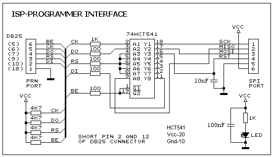
There are five pins on the chip for something called an In-System Programmer, or ISP for short. These pins are used by your computer to program the chip. A common piece of hardware for connecting these ISP pins to one of your PC`s USB ports is the AVRISP mkII. These usually sell for $25 to $30, and are one of the easiest programmers to use. If you don`t feel like going for one of those, you can also build your own Parallel Port ISP programmer without trouble.
There are a number of designs for a parallel programmer, but this is the simplest. Arduino is an AVR-based prototyping board with an emphasis on ease of use. It has breakout headers for I/O pins and power. It also features a USB interface using the FT232RL chip, which allows RS232 serial communication through a USB device, eliminating the need for a separate AVR programmer. The Arduino project also has an Integrated Development Environment for writing AVR code in a C/C+-derived language called Wiring.
The IDE also includes many helpful libraries and a nice function framework. Check out the Arduino website ! The Arduino bootloader will flash Pin 19 (PB5) twice on a 500ms interval at boot-up. The low-power LED is meant for this, or for your own software`s status monitor. Use the 470 ohm resistor in series with the LED. ATmega chips programmed by the Arduino will work as stand-alone microcontrollers. However, in order to use a new ATmega with the Arduino, you must write the Arduino bootloader to the ATmega chip. This can be done with AVRDUDE, UISP, or AVR Studio. See the "Programming your ATmega Chip" section above. ATmega chips running the Arduino bootloader will have a 5 second delay at startup. This is where the bootloader listens for serial data from the Arduino programming environment. If the chip flashes the LED on Pin 13, but never starts executing your code, then place a 10000 ohm resistor between Pin 2 and Pin 3.
The bootloader may "wait" forever because it mistakes noise for data on those pins. Port C interfaces with the TWI (2-Wire or I ²C) module, and provides 6 ADC inputs by interfacing with the A/D Converter module. Port C has 7 I/O pins, and supports pin change interrupts. Analog inputs are on pins PC0 through PC5 🔗 External reference
Related Circuits
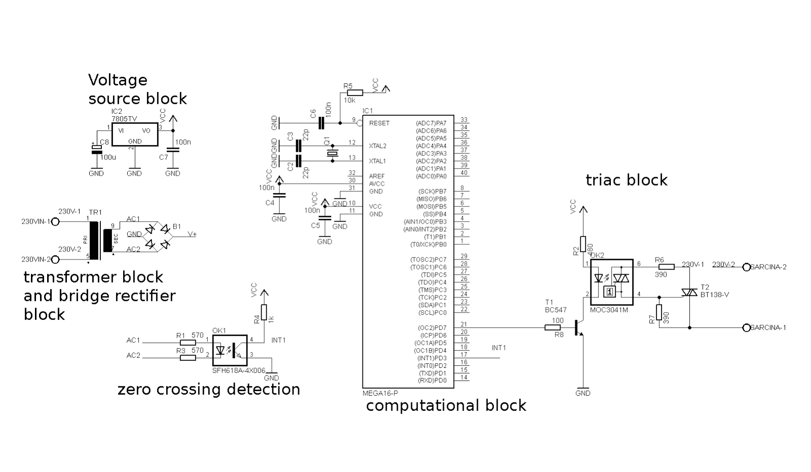
The market offers numerous devices that replace traditional wall switches, allowing for the adjustment of bulb luminosity. For those looking to create an "intelligent" home or a more complex device for controlling light bulb power, several options are available....
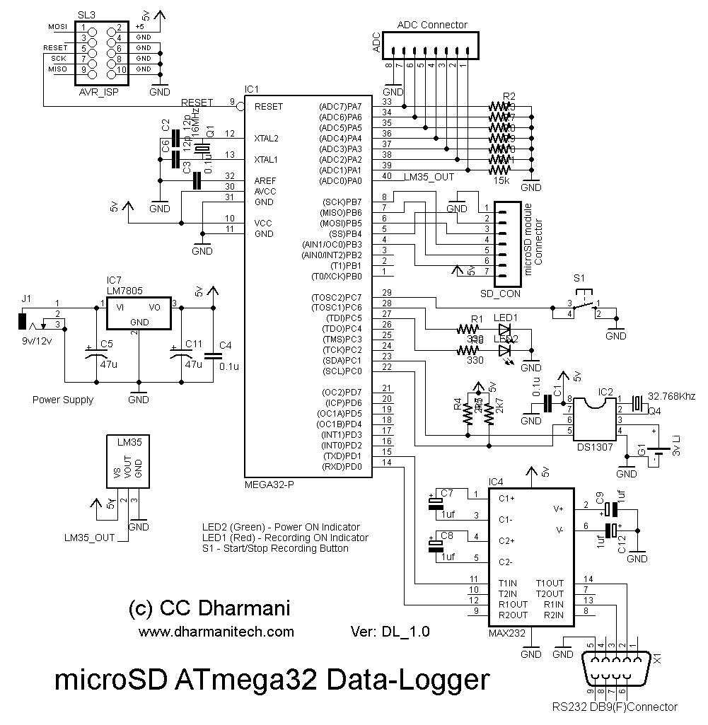
The objective of this project is to demonstrate a method for storing a large amount of data on a microSD card in files formatted with FAT32. The ATmega32 microcontroller is utilized for data collection and interfacing with the microSD...
This is the V2 update of the Atmega8 Volt-Ammeter. This new version features several upgrades, including low power consumption, improved amperage display resolution while using a low-value drop resistor, and a much smaller PCB size of only 5cm x...
This instructable is categorized under 13 - 18 in the National Robotics Week Robot Contest. The National Robotics Week Robot Contest encourages innovation and creativity in robotics among participants aged 13 to 18. This category represents a significant opportunity for...
ISP programmer with circuit diagram for AVR Atmega32 microcontroller. This ISP burner circuit is an adaptation of the Pony programmer and uses PonyProg software. The ISP (In-System Programming) programmer designed for the AVR Atmega32 microcontroller facilitates the programming of the...
A programmer is needed for the ATmega8515 microcontroller, along with a request for information regarding assembly instructions. A parallel programmer for the ATmega8515 microcontroller can be constructed using a few essential components. The ATmega8515 is an 8-bit AVR microcontroller that...