
picaxe 18X repeater controller

The PICAXE-18X repeater controller circuit is designed to facilitate remote operation and control of a VHF repeater system. At its core, the circuit utilizes a PICAXE-18X microcontroller, which operates at a frequency of 4 MHz. This microcontroller is programmed in BASIC, allowing for straightforward coding and adjustments. The circuit is equipped with an MC145436 DTMF decoder chip, which interprets dual-tone multi-frequency signals, enabling remote control functionality for various repeater settings.
The controller features several adjustable parameters, including a time-out timer and ID timer, which can be set to specific durations as required for the repeater's operation. The inclusion of a Morse code identifier allows for automated identification of the station, with the capability to store up to 11 unique identifiers. The design also incorporates a user-friendly interface for programming, utilizing DTMF tones to modify settings without the need for direct access to the microcontroller.
Power management within the circuit is handled by three power MOSFETs, which serve as switches for different components of the repeater system. Two of these MOSFETs are actively used, while one is reserved for future expansion or additional functionality. The circuit includes nine status LEDs, providing real-time feedback on various operational states such as power supply status, carrier-operated relay (COR) activity, and DTMF tone reception. This visual feedback is crucial for troubleshooting and ensuring proper operation of the repeater.
The PCB layout was created using Microsoft Paint, and while this method proved labor-intensive, it demonstrates the feasibility of DIY PCB design without specialized software. The project also highlights the importance of proper printing techniques for transferring the PCB design onto the etching medium, recommending the use of laser printers and specific transfer papers for optimal results.
Overall, this project serves as a practical application of microcontroller technology in amateur radio, showcasing the integration of digital control with traditional radio operations. The design encourages further enhancements and adaptations, inviting collaboration and innovation within the amateur radio community.Decided to quench my curiosity and see if a PICAXE-18X chip running at 4Mhz. was capable of this application. I also wanted to have a go at a project from the ground up. Designing the circuit, drawing up the printed circuit board artwork, etching the circuit board, programming the PICAXE in BASIC and hooking up the circuit board to a couple of surplus VHF radios as a repeater. Being that I am only one of four amateur radio operators in a 300 mile radius that uses our NHRC-4 controlled 2 meter repeater here in the outback in North West Australia, it`s possible that I will never use this circuit. So I encourage anyone to make improvements to any part of this project. The audio section of this project is not my design but was found on another Amateur Radio Operators web site elsewhere on the net.
Thanks K5LXP. Also, I think it was a featured article in the magazine "QST" about 10 years ago. So it seems to be the standard OpAmp audio circuit for a simple PIC approach to controlling a Amateur radio repeater. This project uses a MC145436 DTMF chip for remote control and remote program changes. This basic controller features standard features in many others repeater controllers. Adjustable Time Out Timer, adjustable ID Timer, Morse Code Id`er with 11 available spaces for the call, i.
e. DE_XX#XXX/R, adjustable Hang Timer delay, 3 programmable Roger Beeps, 3 digit password, all programmed in decimal. not HEX! All programmable via DTMF tones once the "BASIC" program has been downloaded into the PICAXE chip with the program and defaults settings.
It also ID`s to a small speaker if required. I found the Speaker Output handy while programming. There are 3 power MOSFETs as switches, 2 used and 1 spare. There are 9 status LED`s for such things as 5 volts OK, COR active, Morse ID, DTMF Tones OK, Mute DTMF Tones, Repeater Muted, PTT Active, Fan ON and a spare status LED for the spare MOSFET switch. Oh, this was very painful. It was all done with the MicroSoft "Paint" program. No special PCB layout software was used. (but I`ve purchased some software now!) It took hours and hours. and more hours to draw up. There are actually two versions. A bare bones PICAXE-08M version and this PICAXE-18X version. The photos of the artwork were. BMP files but they are huge, so I`ve converted them to smaller. JPG files to save a little space on my 20 Megs of free web space. NOTE: One thing I found during this ongoing project was not to print the. BMP artwork file from MS Paint. it`s crap! A helpful hint I found on the internet was to import the large. BMP file into a Word. doc file and resize it to the exact size required before printing. It prints so much better from Word! I`m not sure why But no more crude and jagged edges as when printed from MS Paint. Also, do a test print to paper first and place the18 pin IC socket on it. Make sure the socket pins line up with the socket holes on the paper. If this is correct, all the other part spacing will be OK. Now you`re ready to print to the special blue paper. Printing to the special blue "Press & Peel" paper from a laser printer seems to require a good or new toner cartridge.
The "Press & Peel" people say that using a photocopier machine to transfer pre-printed artwork printed on plain paper, to the special blue "Press & Peel" paper works too, but I haven`t tried the photocopier scheme yet. The repeater controller art w 🔗 External reference
Related Circuits
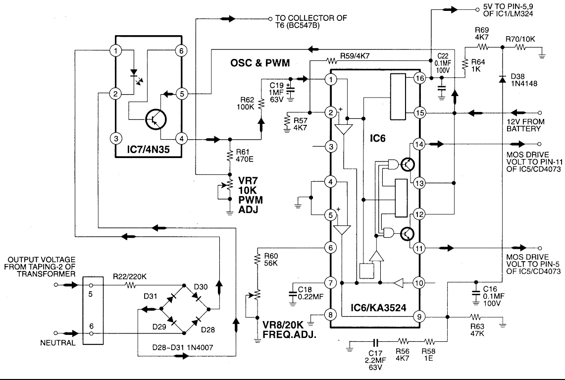
Circuit No. 1 (Oscillator Circuit and Feedback Circuit) Circuit No. 2 (MOS Driver Circuit) Final Product: - Operation of Circuit No. 1 (Oscillator Circuit and Feedback Circuit) This inverter utilizes Pulse Width Modulation (PWM) technology. The working principle of...
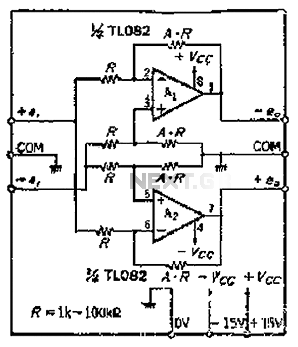
The circuit features a symmetric configuration of two basic differential amplifiers. The differential inputs, labeled +IN and -IN, are connected to ensure balanced input. The output signal components are inverted, resulting in a phase-coherent output. Although the circuit requires...
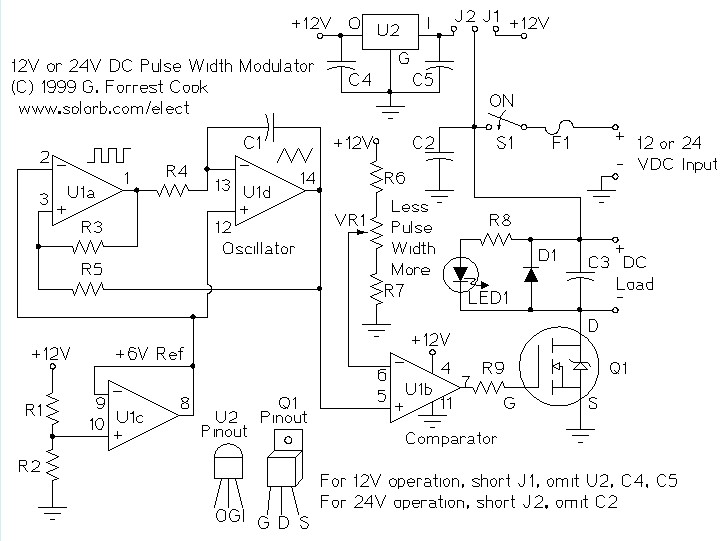
A pulse width modulator (PWM) is a device that can be utilized as an efficient light dimmer or DC motor speed controller. The circuit described here is intended for general-purpose applications, capable of controlling DC devices that draw up...
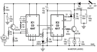
The following circuit illustrates an Infrared Toy Car Motor Controller Circuit Diagram. This circuit is based on the 4017 IC. Features: operating at .. The Infrared Toy Car Motor Controller Circuit utilizes a 4017 Decade Counter IC, which is integral...
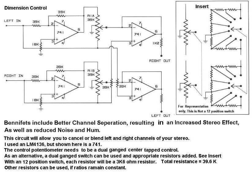
The circuit includes better channel separation, resulting in an increased stereo effect, as well as reduced noise and hum. This schematic will allow you to cancel or blend left and right channels of your stereo. Uses the LM4136 but...

I have been sourcing my MOSFETs from Allied, as they are significantly more affordable than those from Digi-Key. The choice of MOSFETs (Metal-Oxide-Semiconductor Field-Effect Transistors) is crucial in electronic circuit design, particularly in applications requiring efficient switching and amplification. When...