
shortwave radio receiver circuit project

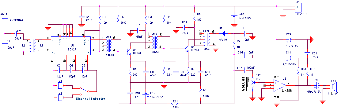
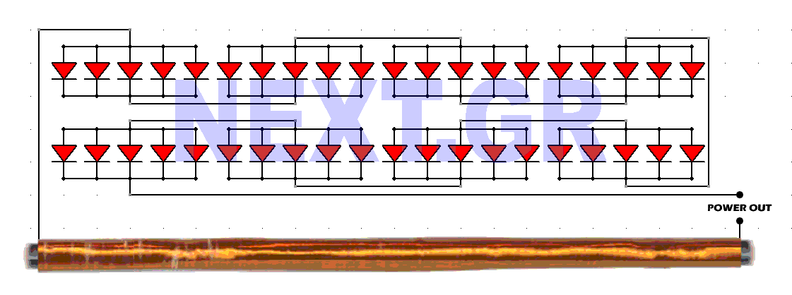
The circuit utilizes a pair of coils, L1 and L2, wound around a PVC pipe to form inductors. The choice of 20-gauge insulated hookup wire ensures adequate current handling and durability. The number of turns in each coil is critical for tuning the circuit to the desired frequency; therefore, the ability to modify the turns or the capacitance value of C2 allows for flexibility in frequency selection.
The amplifier stage, consisting of transistors Q2 and Q3, is designed to provide sufficient gain to drive audio output devices such as headphones or small speakers. This configuration allows for direct amplification of the audio signal detected by diode D1, ensuring that the output signal is strong enough for practical use. The option to replace resistor R3 with a potentiometer introduces a variable resistance that can be adjusted to control the volume level, enhancing user experience.
The inclusion of R4 and C4 as a low-pass filter plays a significant role in maintaining the overall stability of the circuit. This filter effectively attenuates high-frequency noise, which can degrade the audio quality, thus ensuring a cleaner and more enjoyable listening experience.
Furthermore, the voltage regulation aspect of the circuit is managed by diodes D2, D3, and D4. This arrangement provides a stable voltage supply to the amplifier (Q1), which is crucial for consistent performance. By minimizing voltage drift, the circuit achieves reliable operation over varying conditions, which is particularly important in audio applications where fluctuations can lead to distortion or other undesirable effects.
Overall, this circuit design exemplifies a practical approach to audio amplification, incorporating essential features for tuning, stability, and user control, making it suitable for various audio applications.All coils are designed using an inch diameter pvc pipe using 20 gauge insulated hookup wire, L1 require 6 turns and L2 require 14 turns. You can add turns to or subtract turns from L(or change C2) to receive other frequencies. Q2 and Q3 form an amplifier, which has sufficient output level to directly drive headphones or a small speaker, amplify
the detected audio signal output from D1. R3 can replaced with a 2kohms potentiometer, if you want to use it as an volume control. R4 and C4 form a lowpass filter that maintains circuit stability and improves the receiver`s sound quality. D2, D3, and D4 implement a low-cost voltage regulator to keep the voltage supplying Q1fairly constant, which minimizes drift.
🔗 External reference
Related Circuits
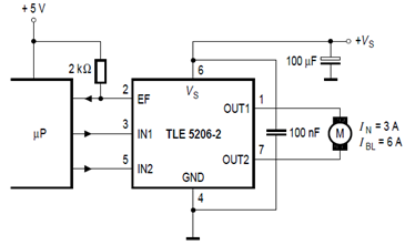
The schematic below illustrates the TLE5206-2 5A H-Bridge circuit for DC motor applications. This device features an integrated power H-bridge with DMOS output stages designed specifically for driving DC motors, as indicated in the datasheet. The TLE5206-2 circuit application...
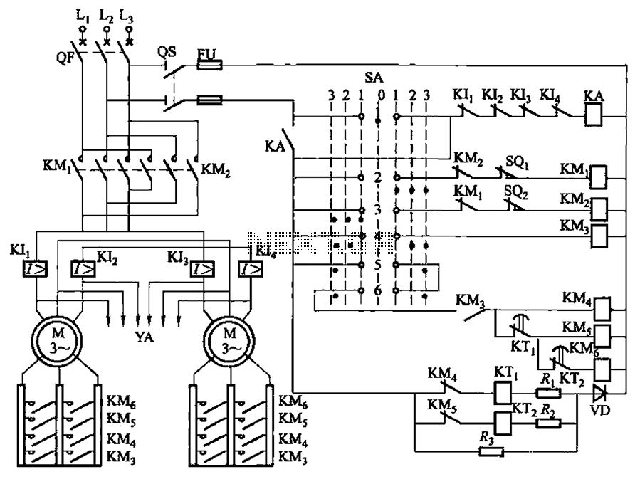
The LK16-5/31 type master controller and PQY2 Series Magnetic control panel comprise a control circuit. The PQY2 series control panel, along with the magnetic PQY1 control panel, features a similar control circuit. The electrical components are fundamentally the same;...
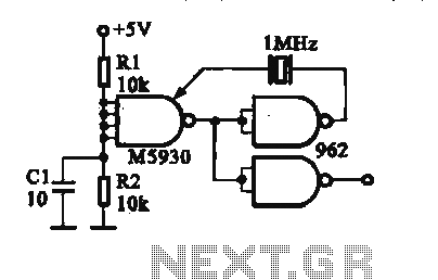
A crystal oscillator is implemented using a DTL (Diode-Transistor Logic) integrated circuit. The oscillation frequencies are 100 kHz and 1 MHz. The circuit consists of a gate circuit that generates a signal for the oscillator circuitry in DTL. The crystal...
For the regulation needs a transmitter or generator in mpa'nta the CB, that is to say in the region 27MHz. If you have a certain friend with CB, you convince you to help. Connect a piece of cable around...
This schematic converts surrounding radio waves into usable electrical current. The power levels can be increased by incorporating additional diodes. The key factors in this device are the type of diodes used and the construction of the antenna. The...
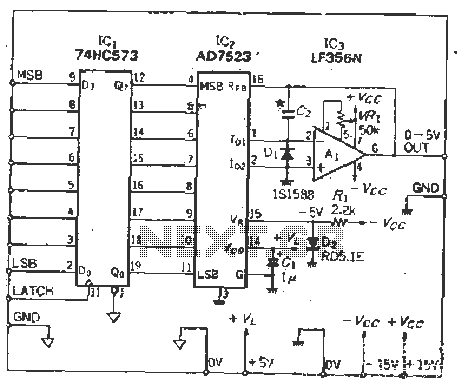
The IC latch is utilized to hold the digital data when the clock signal rises. The configuration includes a holding data port AD7s23, a thin film resistor ladder, and a switch that together form an 8-bit Digital-to-Analog Converter (DAC)....