
Crystal oscillator DTL integrated circuit

The crystal oscillator circuit operates by utilizing the piezoelectric properties of a quartz crystal, which provides a stable frequency reference. In this design, the DTL integrated circuit plays a crucial role in generating the oscillation signal. The DTL technology is known for its high-speed operation and low power consumption, making it suitable for applications requiring reliable frequency generation.
The circuit is typically configured with a feedback loop that connects the output of the gate circuit back to its input through the crystal. This feedback ensures that the oscillation is sustained at the desired frequency. The choice of oscillation frequencies, such as 100 kHz and 1 MHz, allows the oscillator to be used in various applications, including clock generation for digital circuits, frequency modulation, and signal processing tasks.
The gate circuit within the DTL integrated circuit consists of a combination of diodes and transistors that work together to create the necessary conditions for oscillation. The diodes provide the necessary biasing for the transistors, which amplify the signal and maintain the oscillation. The output signal can be further processed or used directly in the application, depending on the requirements.
Overall, this crystal oscillator design exemplifies the integration of DTL technology with crystal oscillation principles, resulting in a compact and efficient frequency generation solution.By a crystal oscillator b DTL integrated circuit constituted DTL is shown by the crystal oscillator integrated circuits, and the oscillation frequency is 100 kHz and 1 MHz. It is constituted by a gate circuit to provide a signal for the oscillator circuitry DTL.
Related Circuits
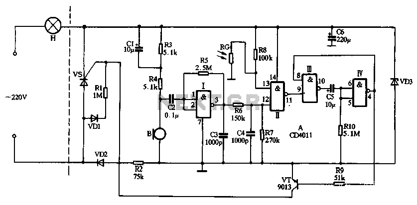
The circuit utilizes CD4011 digital circuits to create a sound-activated light lamp with a dual-control delay section. The left portion of the circuit represents the lighting lines, while the right part consists of the sound and light control delay...
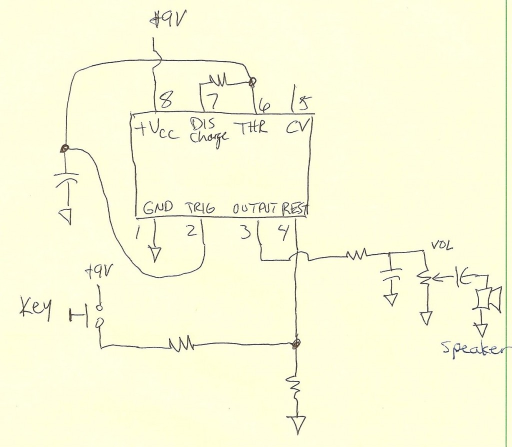
A code practice oscillator was built some time ago, and there is a vague recollection of the project. It featured a straight key that plugged directly into the key jack. Upon opening the device, a circuit board populated with...
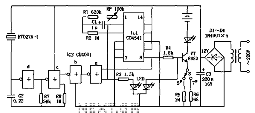
The CD4001/CD4541 nickel-cadmium battery automatic charger circuit is illustrated in the figure. This circuit is designed for charging up to seven rechargeable nickel-cadmium batteries. It features automatic charging with constant current characteristics. Once powered, the circuit activates an internal...
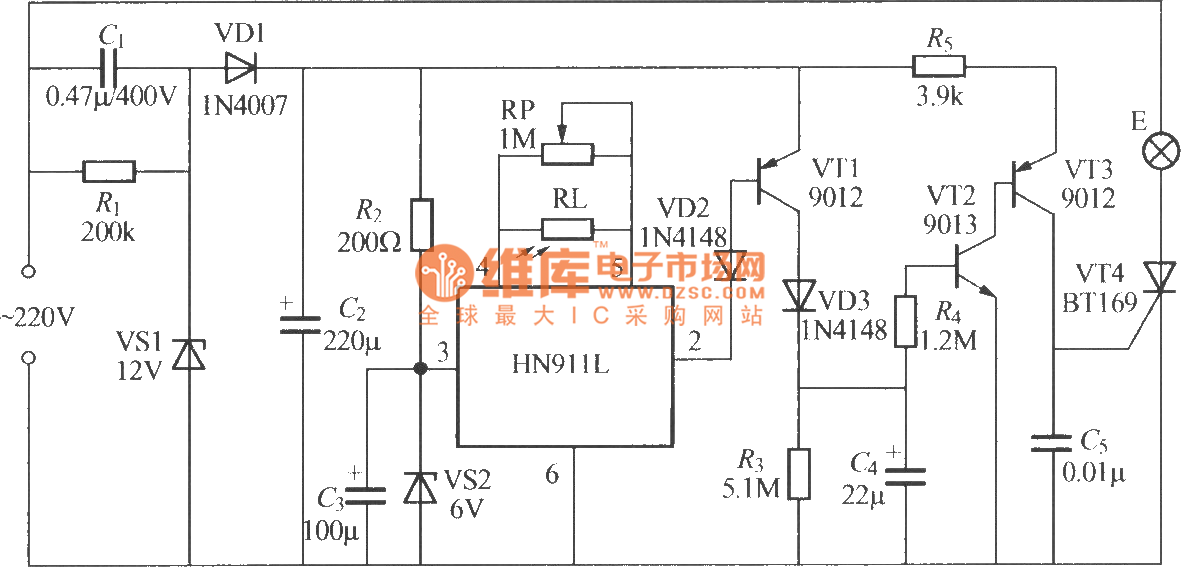
The figure illustrates an automatic light sensing system utilizing the HN911L pyroelectric infrared detection module. The HN911L incorporates high-sensitivity infrared sensors, a passive infrared (PIR) sensor, amplifiers, a signal processing circuit, and an output circuit. This module is capable...
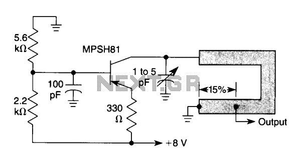
This oscillator is typical for operation between 350 to 500 MHz. The microstrip inductor is implemented as a printed circuit board (PCB) trace. The output power ranges from 55 to 100 mW into a 50-ohm load, with frequency stability...
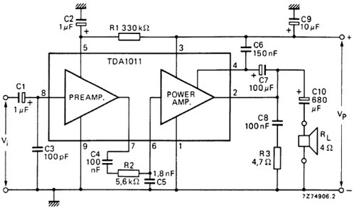
The following schematic illustrates the design of a 4 Watt Amplifier Circuit Diagram intended for portable radio applications, utilizing the TDA1011 integrated circuit from Philips Semiconductor. The 4 Watt Amplifier Circuit is designed to provide audio amplification in portable radio...