
to verify schematics for 2 motor robot

To modify the circuit for the use of more powerful motors, several steps must be taken. First, it is essential to select motors that match the desired specifications in terms of voltage and current ratings. The power supply must be upgraded to accommodate the increased power requirements of the new motors. This may involve using a higher voltage battery or a more robust power supply unit that can deliver the necessary current without causing voltage drops.
Next, the motor driver circuitry must be evaluated. The existing motor driver may not support the higher current ratings of the new motors. It may be necessary to replace it with a motor driver that can handle the increased load. For example, an H-bridge driver capable of managing the peak current of the new motors should be chosen. Proper heat dissipation mechanisms, such as heat sinks or active cooling, may also be required to prevent overheating during operation.
Regarding the construction of a Segway prototype using the same circuit, it is indeed feasible, as both applications utilize two motors for propulsion. However, additional components will need to be integrated to achieve self-balancing functionality. A gyroscope and accelerometer combination is typically employed for this purpose. The gyroscope provides angular velocity data, while the accelerometer measures linear acceleration. Together, they can give a comprehensive understanding of the vehicle's orientation and motion.
To implement self-balancing, a Kalman filter can be utilized to process the sensor data. The Kalman filter will help in estimating the state of the system, filtering out noise, and providing a more accurate representation of the vehicle's tilt angle. The output from the Kalman filter can then be used to adjust the motor speeds dynamically, ensuring that the vehicle maintains its balance.
In summary, modifying the circuit for more powerful motors involves upgrading the power supply and motor driver, while building a Segway prototype requires the integration of sensors and a Kalman filter for self-balancing capabilities. Proper design considerations must be taken into account to ensure that the system operates effectively and safely.Constructing a robot or should i say a vehicle dat uses 2 motors. I managed to get sum referance regarding d schematics for the circuit design but the current schematics uses a smaller motor. which draws less power and uses a much less power supply. the schematics is in the link below. i need to use a much powerful motor and provide more power to the circuit. cn anyone provide some explanation on howto modify the circuit. thankz a lot! jz another question. cn i build a segway using the same circuit. im planning 2 do a segway prototype. since this circuit also uses 2 motors. izit d same n if it is the sam. how do i add a gyro and a kaplan filter in it. in provide self-balance for the robot. 🔗 External reference
Related Circuits
4QD manufactures motor speed controllers, and all their H bridges utilize PWM. This is a simple switch circuit designed for reversing and stopping a motor without speed control. Two inputs, A and B, control the bridge. When both inputs...
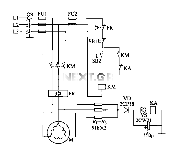
Delta connection motor phase failure protection circuit is illustrated in the figure. Its protective function involves three resistors, R1, R2, and R3, which are connected to form an artificial neutral point. When a motor phase failure occurs, an offset...

The figure illustrates a circuit involving dark tomb electric locks, specifically the fti: al: 4046B and XOR gate as the primary control mechanism. It emits pulses and utilizes silicon for successive pulse generation. The circuit operates with a normal...
This information pertains to a dosing pump control circuit that utilizes the LM317 integrated circuit (IC). The circuit operates with a power supply of 24V DC and is capable of adjusting the output voltage to 1.25V. The LM317 is a...
To achieve a low-cost, accurate, and simple position control system, a stepper motor can be utilized. A circuit designed to drive the motor should be mounted in proximity to the motor itself. Stepper motors are widely employed in applications requiring...
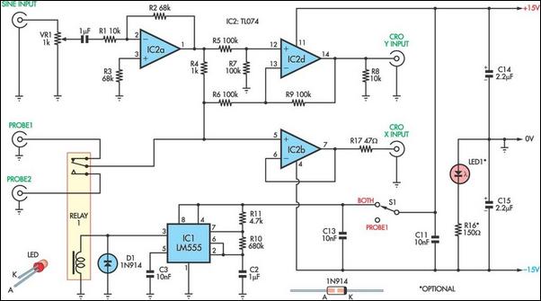
This unit utilizes a dual trace oscilloscope with X-Y functionality as a display to test and demonstrate the operation of circuits and components such as transistors, diodes, zener diodes, and both terminated and unterminated transformers. A low-frequency sine wave...