
univibe pedal circuit diagram
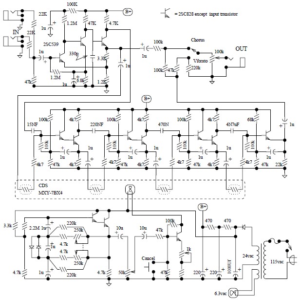
The Univibe circuit operates by modulating the phase of the input signal to create a rich, swirling effect that is reminiscent of a Leslie speaker. The modulation is typically achieved using a combination of light-dependent resistors (LDRs) and a light source, often a bulb. The LDRs change their resistance based on the intensity of the light, which is modulated by the bulb, creating the desired phasing effect. The circuit may include a depth control to adjust the intensity of the modulation and a speed control to vary the rate of the effect, allowing for versatile sound shaping.
The octave fuzz circuit is designed to produce a distinct octave effect alongside a fuzz tone. The key components include transistors configured to create a rectified signal, which contributes to the chewy texture of the fuzz. The optional mode allows users to select between the full octave fuzz and a standard fuzz effect, making it adaptable for different musical styles.
The DOD FX75 Flanger circuit employs a Bucket Brigade Device (BBD) to achieve a time delay effect, which is modulated to create a flanging sound. The use of a low-noise BBD ensures that the signal remains clean while the delay is manipulated. The TL022C op-amp is used to amplify the signal, while the CD4007 provides the necessary analog switching capabilities.
The Tube Distortion Pedal circuit utilizes a dual op-amp configuration to amplify the guitar signal before it is distorted. The LM340K-12V Voltage Regulator ensures stable operation of the circuit by providing a consistent voltage supply, critical for maintaining sound quality.
The Univox Super-Fuzz Pedal circuit employs a unique design that allows for octave generation through a differential amplifier configuration. This design provides a distinctive sound that has contributed to its popularity among guitarists seeking a unique tonal character.
The Maestro Boomerang/Wah-Wah Pedal circuit is designed to provide a wah effect, which is achieved by varying the frequency response of the signal. The use of specific transistors enables the pedal to produce a wide range of tonal variations, making it a versatile tool for guitarists looking to enhance their sound. Detailed construction instructions provide guidance for builders to replicate this classic effect.The Univibe is actually a footpedal-operated phaser or phase shifter for generating chorus and vibrato simulations for electric organ or guitar. It was introduced in the 1960s by Shin-ei, and was intended to emulate the "Doppler sound" of a Leslie speaker.
Although not a really successful Leslie-simulator, the Univibe has turn out to be an. Here the circuit diagram of octave fuzz guitar effect pedal. This guitar effect unit is great sounding octave fuzz, with an optional mode of just fuzz. The fuzz is really a absolutely rectified signal and is fairly chewy. For some the Fuzz alone could possibly not be loud enough, this could be fixed by raising. This is the circuit diagram of DOD FX75 Flanger guitar effect pedal. The circuit drawn by Fabian P. Hartery Components CD4007 dual complementary pair with inverter; (RCA) TL022C low power dual operating amplifier; (texas instruments) MN3007 audio signal delay, 1024 stage low noise BBD (5. 12-51. 2 msec delay) MN3101 clock generator for Bucket Brigade Device/BBD. The following circuit is Tube Distortion Pedal for guitar effect. The circuit designed by Ron Black. Notes: IC1 : 747 dual op-amp, other ICs may be substitued but pinout will different. You should check the datasheet IC2 : LM340K-12V Voltage Regulator All resistors are 1/2 W Bridge Rectifier - Full wave bridge recitifier, 50 Volts, .
This is the circuit diagram of Univox Super-Fuzz Pedal. This pedal is actually a 69-to-early 70`s design that consists of two special capabilities. They are the octave generation effect from the differential-pair-with-collectors -tied-together along with the option of just a clipping amplifier or a 1kHz notch for different sounds. The odd-diffamp is basically a full. Here the circuit diagram of Maestro Boomerang / Wah-Wah Pedal for electric guitar effect. Note: Transistors Q1 and Q2 were designated P-2356 Download schematic in pdf document HERE Step by step about how to build Maestro Boomerang Wah Pedal guitar effect, visit this page
🔗 External reference
Related Circuits
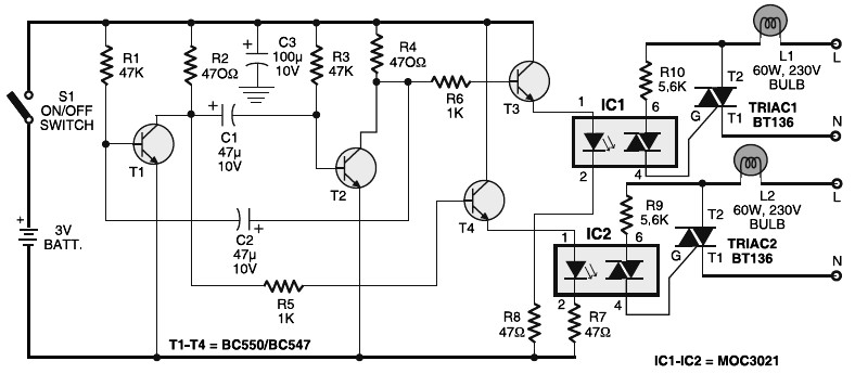
Portable 230V lamp flasher circuit diagram. The circuit is entirely transistorized and powered by a battery. A free-running oscillator circuit is implemented using two low-power, low-noise transistors, T1 and T2. One of these transistors remains in a conducting state...
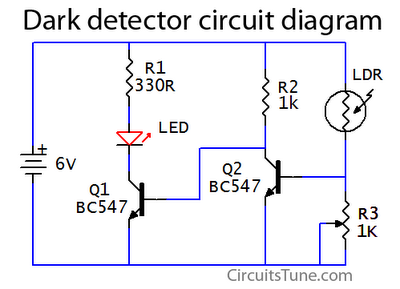
This is a basic dark detector or sensor circuit diagram based on a photoresistor (LDR) and a few components. The dark detector circuit utilizes a photoresistor (LDR) as the primary sensing element. The LDR is a light-dependent resistor that changes...
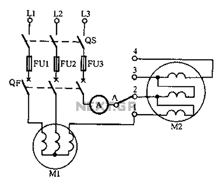
Below is a circuit diagram for detecting motor winding current imbalance during the drying process. The circuit diagram is designed to monitor the current flowing through the windings of a motor used in drying applications. This imbalance detection is crucial for...
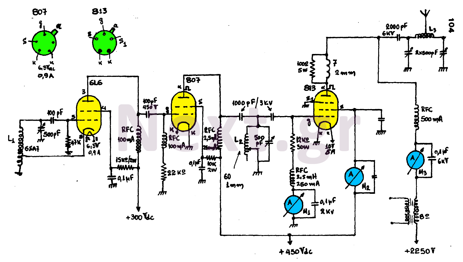
The circuit consists of three main stages and provides the antenna with a power output of 300 watts, contingent upon proper tuning. The first stage is an oscillator featuring an oscillating coil L1, which is commercially available as a...
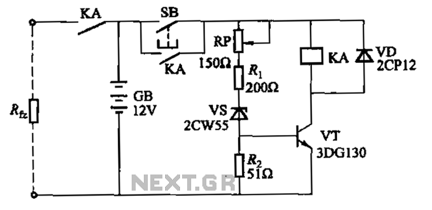
Deep discharge of a battery can lead to plate curing, which shortens the battery's lifespan. To prevent this, a discharge protection device can be implemented. The circuit diagram illustrates this mechanism. When the battery voltage falls to a predetermined...
To achieve optimal audio reproduction at varying listening levels, it is essential to adjust tone control settings to align with the established characteristics of human auditory perception. The sensitivity of the human ear changes non-linearly across the entire audible...