
CMOS Toggle Flip Flop Switch

The circuit employs a CMOS dual D flip-flop (CD4013) configured to toggle a relay or load in response to a momentary push button input. The use of CMOS technology allows for low power consumption and high noise immunity. The momentary push button provides a high signal that is coupled to the set line of the flip-flop through a 0.1 µF capacitor, which serves to filter any rapid fluctuations in the signal, effectively debouncing the switch.
When the push button is pressed, the set line receives a high signal, causing the flip-flop to set its Q output high. This high signal is then inverted by a transistor, which pulls the reset line low for approximately 400 milliseconds, allowing the circuit to stabilize before the reset line returns to a high state. This timing ensures that the flip-flop is reset after a brief period, preventing unintended toggling.
The lower section of the flip-flop is configured to toggle its state on the rising edge of the clock signal. This configuration allows the circuit to maintain its state until the next push button press, thereby enabling multiple push buttons wired in parallel to control the relay from various locations.
Due to the limited current output of the Q and Qbar (approximately 2 mA), an additional buffer transistor or power MOSFET is necessary for driving larger loads, such as relay coils or lamps. For loads with resistance greater than 250 ohms, a small-signal NPN transistor like the 2N3904 is suitable. For lower resistance loads, a medium power transistor like the 2N3053 should be utilized to handle the increased current demand.
The circuit is further stabilized by a 47-ohm resistor and a 10 µF capacitor, which work together to decouple the circuit from the power supply and filter out noise. An RC network comprising a 0.1 µF capacitor and a 47 kΩ resistor at the SET line provides a power-on reset feature, ensuring that the relay remains de-energized immediately upon powering the circuit. This design enhances reliability and usability, making it an effective solution for controlling loads from multiple locations.The circuit below uses a CMOS dual D flip flop (CD4013) to toggle a relay or other load with a momentary push button. Several push buttons can be wired in parallel to control the relay from multiple locations. A high level from the push button is coupled to the set line through a small (0.1uF) capacitor. The high level from the Q output is inverted by the upper transistor and supplies a low reset level to the reset line for about 400 mS, after which time the reset line returns to a high state and resets the flip flop.
The lower flip flop section is configured for toggle operation and changes state on the rising edge of the clock line or at the same time as the upper flip flop moves to the set condition. The switch is debounced due to the short duration of the set signal relative to the long duration before the circuit is reset. The Q or Qbar outputs will only supply about 2 mA of current, so a buffer transistor or power MOSFET is needed to drive a relay coil, or lamp, or other load.
A 2N3904 or most any small signal NPN transistor can be used for relay coil resistances of 250 ohms or more. A 2N3053 or medium power (500 mA) transistor should be used for coil resistances below 250 ohms. The 47 ohm resistor and 10uF capacitor serve to decouple the circuit from the power supply and filter out any short duration noise signals that may be present.
The RC network (.1/47K) at the SET line (pin 8) serves as a power-on reset to ensure the relay is denergized when circuit power is first applied. The reset idea was suggested by Terry Pinnell who used the circuit to control a shed light from multiple locations.
🔗 External reference
Related Circuits
This analog switch utilizes the 2N4860 JFET, which features a low on-resistance (rON) of 25 ohms and minimal leakage current. The LM102 acts as a voltage buffer in the circuit. It is designed to be adaptable for use in...
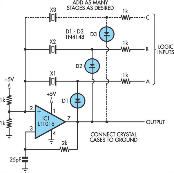
This oscillator circuit allows crystals to be electronically switched through logic commands. The circuit is best comprehended by initially disregarding all crystal components. The oscillator circuit described functions as a frequency generator that utilizes the properties of quartz crystals to...
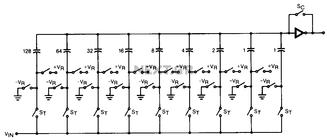
The CMOS comparator in the successive-approximation system determines each bit by examining the charge on a series of binary-weighted capacitors. In the first phase of the conversion process, the analog input is sampled by closing switch SC and all...

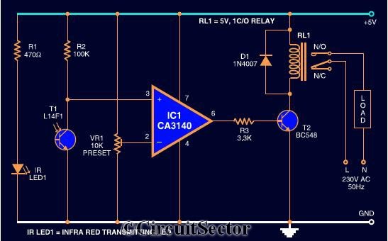
Infrared Remote Control Switch Circuit. Remote controls, particularly cordless types, have gained significant popularity in recent times. This document presents a simple infrared remote control switch circuit. The infrared remote control switch circuit utilizes an infrared (IR) transmitter and receiver...
The circuit diagram presented is a highly sensitive wireless relay switch designed to control home appliances such as flush systems and hand dryers. This wireless switch operates without the need for a remote control. It functions by simply moving...
The circuit of the mains current detector is shown in Figure 1. By using a few cheap diodes, a resistor, LED and LDR, a simple opto-isolated detector can be created. This entire circuit dissipates very low power, and can...