
Colpitts oscillator

The Colpitts oscillator circuit is characterized by its use of a feedback loop that integrates a parallel LC circuit, which is pivotal for determining the oscillation frequency. The configuration typically employs a transistor, which can be either a bipolar junction transistor (BJT) or a field effect transistor (FET), as the active gain component. The feedback mechanism is crucial for sustaining oscillations, and the arrangement of capacitors C1 and C2, along with inductor L, forms the resonant tank circuit. This tank circuit is responsible for the oscillator's frequency response, which can be finely tuned by adjusting the inductance or capacitance values.
In practical applications, the Colpitts oscillator is often favored for its simplicity and effectiveness in generating stable frequencies. The choice of components, including the active device and passive elements, directly influences the performance characteristics, such as frequency stability and output waveform quality. The circuit's design allows for flexibility in tuning methods, accommodating both variable inductance and capacitance configurations, which is advantageous for applications requiring precise frequency adjustments.
The analysis of the Colpitts oscillator can be approached through various methods, including input impedance analysis, which provides insights into the conditions necessary for oscillation. The presence of negative resistance is a key indicator of the circuit's potential to oscillate, and careful consideration of the active component's gain relative to the feedback network's attenuation is essential for stable operation. Overall, the Colpitts oscillator remains a fundamental circuit in the field of electronics, widely utilized in RF applications and signal generation tasks due to its robust performance and design versatility.The Colpitts circuit, like other LC oscillators, consists of a gain device (such as a bipolar junction transistor, field effect transistor, operational amplifier, or vacuum tube ) with its output connected to its input in a feedback loop containing a parallel LC circuit ( tuned circuit ) which functions as a bandpass filter to set the frequency o f oscillation. A Colpitts oscillator is the electrical dual of a Hartley oscillator, where the feedback signal is taken from an "inductive" voltage divider consisting of two coils in series (or a tapped coil). Fig. 1 shows the common-base Colpitts circuit. L and the series combination of C1 and C2 form the parallel resonant tank circuit which determines the frequency of the oscillator.
The voltage across C2 is applied to the base-emitter junction of the transistor, as feedback to create oscillations. Fig. 2 shows the common-collector version. Here the voltage across C1 provides feedback. The frequency of oscillation is approximately the resonant frequency of the LC circuit, which is the series combination of the two capacitors in parallel with the inductor As with any oscillator, the amplification of the active component should be marginally larger than the attenuation of the capacitive voltage divider, to obtain stable operation.
Thus, a Colpitts oscillator used as a variable frequency oscillator (VFO) performs best when a variable inductance is used for tuning, as opposed to tuning one of the two capacitors. If tuning by variable capacitor is needed, it should be done via a third capacitor connected in parallel to the inductor (or in series as in the Clapp oscillator ).
Fig. 3 shows a working example with component values. Instead of bipolar junction transistors, other active components such as field effect transistors or vacuum tubes, capable of producing gain at the desired frequency, could be used. One method of oscillator analysis is to determine the input impedance of an input port neglecting any reactive components.
If the impedance yields a negative resistance term, oscillation is possible. This method will be used here to determine conditions of oscillation and the frequency of oscillation. An ideal model is shown to the right. This configuration models the common collector circuit in the section above. For initial analysis, parasitic elements and device non-linearities will be ignored. These terms can be included later in a more rigorous analysis. Even with these approximations, acceptable comparison with experimental results is possible. If an inductor is connected to the input, the circuit will oscillate if the magnitude of the negative resistance is greater than the resistance of the inductor and any stray elements.
The frequency of oscillation is as given in the previous section. For the example oscillator above, the emitter current is roughly 1 mA. The transconductance is roughly 40 mS. Given all other values, the input resistance is roughly This value should be sufficient to overcome any positive resistance in the circuit. By inspection, oscillation is more likely for larger values of transconductance and smaller values of capacitance.
A more complicated analysis of the common-base oscillator reveals that a low frequency amplifier voltage gain must be at least four to achieve oscillation. [6] The low frequency gain is given by: If the two capacitors are replaced by inductors and magnetic coupling is ignored, the circuit becomes a Hartley oscillator.
In that case, the input impedance is the sum of the two inductors and a negative resistance given by: This assumes that the transistor does not saturate, the collector current flows in narrow pulses, and that the output voltage is sinusoidal (low distortion). Ulrich L. Rohde, Ajay K. Poddar, Georg B ck "The Design of Modern Microwave Oscillators for Wireless Applications ", John Wiley & Sons, New York, NY, May, 2005, ISBN 0-471-72342-8.
George Vendelin, Anthony 🔗 External reference
Related Circuits
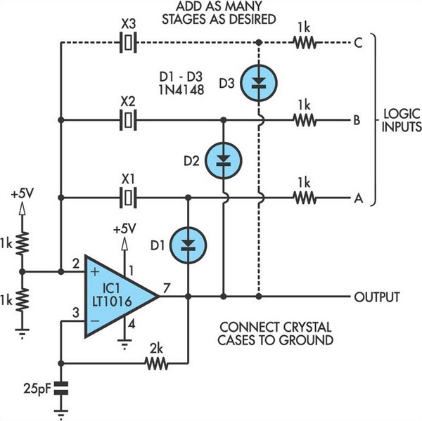
This oscillator circuit allows crystals to be electronically switched through logic commands. The circuit is best comprehended by initially disregarding all crystal components. The oscillator circuit described functions as a frequency generator that utilizes the properties of quartz crystals to...
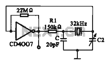
A 32 kHz clock oscillator is essential for digital circuits, as depicted in the schematic. The 32 kHz crystal clock oscillator serves to provide a time reference signal for the digital circuit. It utilizes a CMOS integrated circuit, specifically...
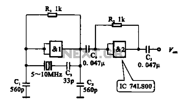
A crystal oscillator circuit comprises various gates as illustrated in the provided figures. Figure (A) represents a crystal oscillator circuit operating at 1 MHz, while figure (B) depicts a 20 MHz crystal oscillator circuit. Figure (C) shows a variable...
An audio test oscillator circuit typically produces a square wave if the oscillation frequency is low enough in relation to the amplifier's bandwidth. This circuit features a crystal-controlled oscillator designed for low-frequency sine wave generation, characterized by low distortion,...
Figure 1 illustrates the VFO oscillator circuit operating within the frequency range of 10.58 to 10.74 MHz. This circuit is a redesigned version of a previously presented Colpitts oscillator, with a clearer representation. The inductor, labeled "L," has an...
The voltage Vc1 increases linearly when the pull-up resistor RA in the monostable circuit is replaced with a constant current source, resulting in a linear ramp. The circuit for generating the linear ramp and the corresponding waveforms are illustrated...