
PC RS485 Interface
The RS485 interface circuit is designed to facilitate robust, long-distance communication between a PC and RS485-compatible devices while ensuring electrical isolation to protect sensitive equipment from high voltages. The circuit typically includes a differential driver and receiver, which enable the transmission of data over twisted pair cables, reducing susceptibility to noise and allowing for multiple devices to share the same bus.
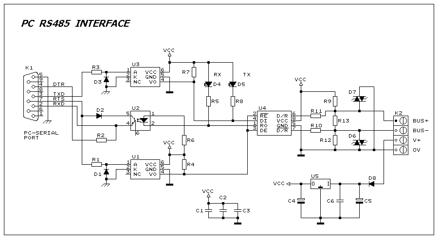
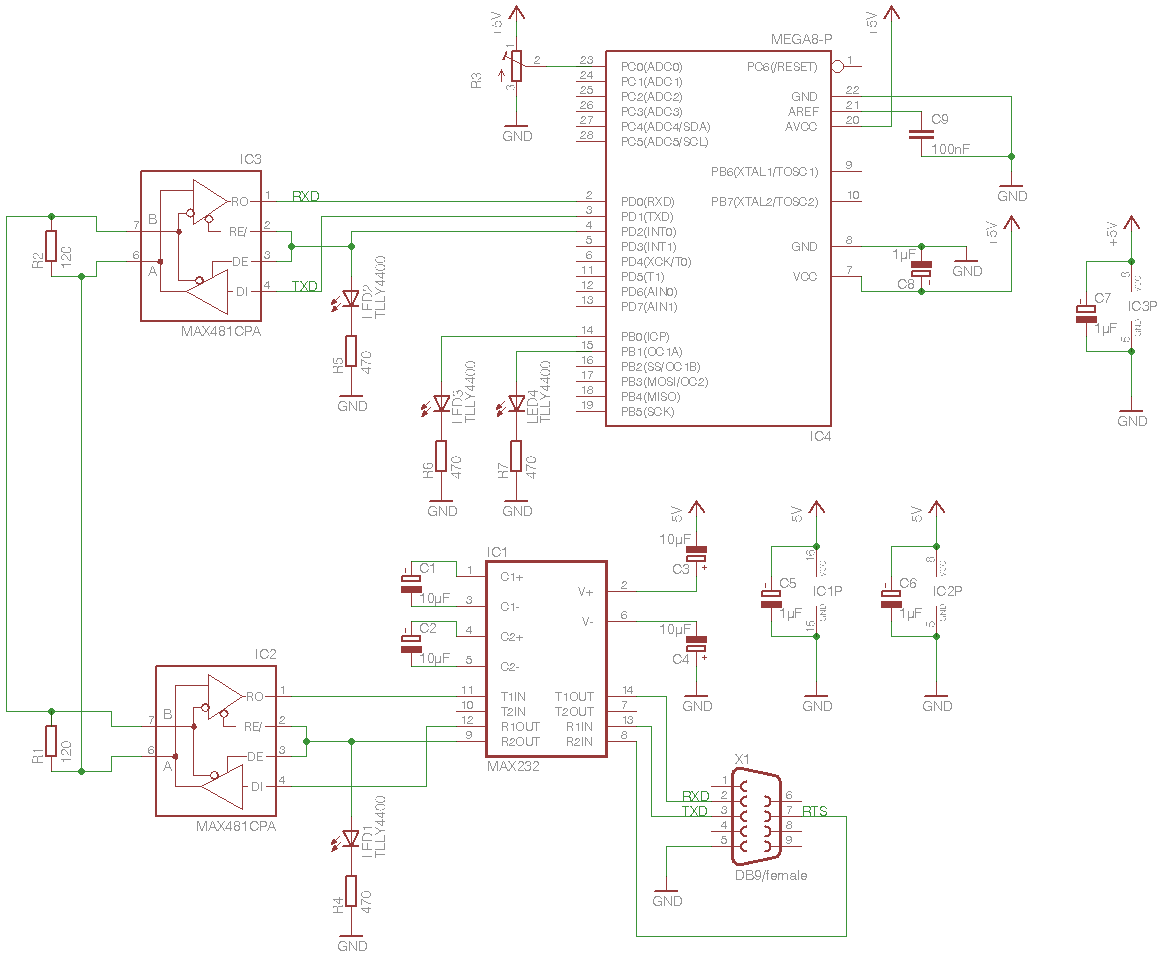
Connector K1 is the interface point for the PC's serial port, which connects to the DTR (Data Terminal Ready) and RTS (Request to Send) lines. These lines are used to derive the power supply necessary for the RS485 communication. The RTS line provides a positive voltage supply, while the DTR line is used to establish a negative voltage supply, ensuring that the interface circuit has the necessary operating voltages to function correctly.
The isolation circuit is a critical component of this design, typically implemented using opto-isolators or isolation transformers. This isolation prevents any hazardous voltages present on the RS485 side from reaching the PC, thereby protecting its components and ensuring reliable operation even in electrically noisy environments.
The RS485 transceiver, which is a key component of the circuit, converts the single-ended signals from the PC into differential signals suitable for RS485 communication. This transceiver is capable of driving the twisted pair lines and receiving signals from connected devices. The circuit may also include termination resistors to minimize signal reflections and ensure signal integrity over long distances.
Overall, this RS485 interface circuit is essential for applications requiring reliable communication over extended distances while maintaining electrical safety and protecting the connected devices.This interface circuit provides electrically isolated RS485 communication inteface to the PC serial port the isolation circuit protect the PC from direct connection to hazardous voltages. Figure 1 shows the circuit diagram of RS485 interface. Connector K1 is linked to the serial port of the PC, power to the PC side of the circuit is derived from the signal lines DTR and RTS. Positive supply is derived from RTS and negative supply from the 🔗 External reference
Related Circuits
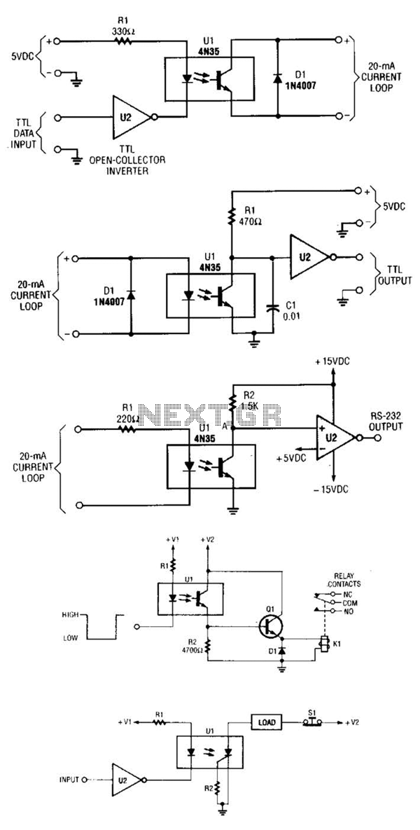
A circuit for isolating a variable resistor is presented. An optoisolator, which consists of an LED and a photo-conductive cell (or photoresistor), is utilized. The current flowing through the LED regulates its brightness, which subsequently dictates the resistance between...

The relay power in the linear circuit is derived from a -120 V bias supply, while the transmit keying output from the Kenwood device is +12 V with a maximum current of 10 mA. A critical component of this...
This smartcard adapter follows exactly the specification ISO 7816. Also, the protocol is the "asynchronous half duplex T=0 protocol" with "active low reset" and "inverse convention" as defined in this standard. The following description may be used in order...
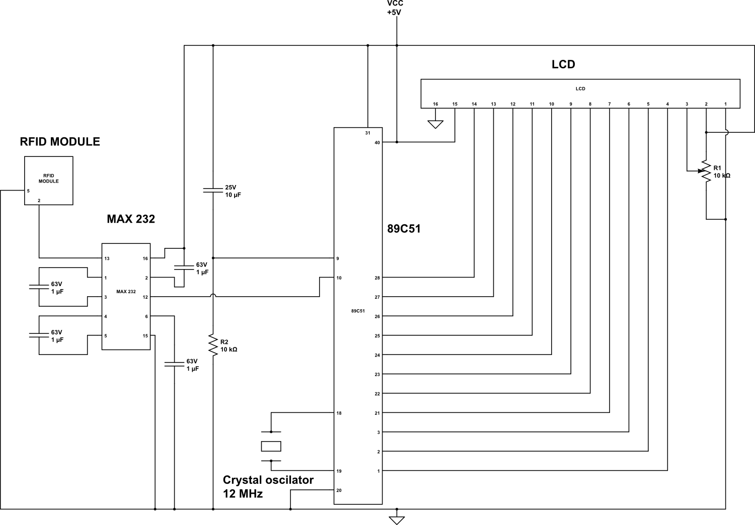
An RFID (Radio-frequency identification and detection) reader is a device used to communicate with RFID tags by receiving and transmitting signals. These signals utilize radio waves for wireless communication. RFID tags are applied to products, individuals, or animals for...
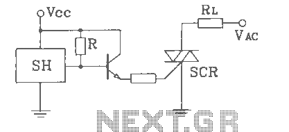
SH Hall opened with a double silicon output interface circuit The SH Hall sensor circuit is designed to provide a dual silicon output interface, which enables enhanced signal processing capabilities. This circuit typically integrates a Hall effect sensor that detects...
This project implements a half-duplex, master/slave communications protocol based on RS-485 bus hardware. A Windows PC acts as the bus-master, while several Atmel 8-bit AVRs function as bus-slaves. The Windows component is developed in C++, with the ninth data...