
connect a lcd to the bottom half of a port

The circuit involves interfacing a 16x2 LCD with a PICAXE-18M2 microcontroller, utilizing the lower half of a specified port for data communication. The LCD operates in 4-bit mode, which is advantageous for reducing the number of data lines required for communication, thus optimizing the circuit layout.
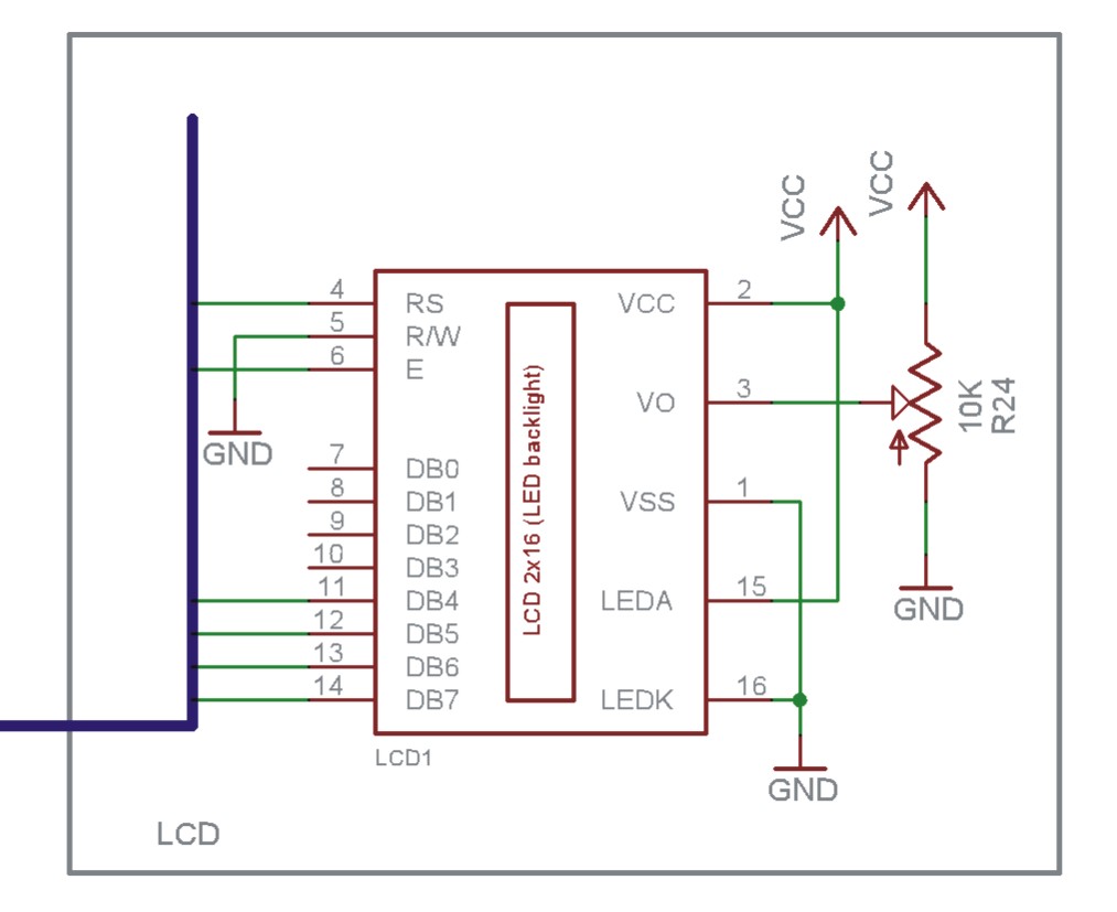
To establish the connection, the following pins of the LCD are utilized: RS (Register Select), RW (Read/Write), E (Enable), and four data pins (D4, D5, D6, D7). The PICAXE-18M2 microcontroller will interface with these pins as follows:
1. **RS Pin**: Connect to a designated output pin on the microcontroller, typically used to select between command and data modes.
2. **RW Pin**: This pin can be connected to ground, as the microcontroller will only be writing data to the LCD.
3. **E Pin**: Connect to another output pin on the microcontroller, used to enable the LCD to read the data presented on the data pins.
4. **Data Pins (D4-D7)**: Connect these pins to four output pins on the PICAXE-18M2, allowing for the transmission of data in 4-bit mode.
Power supply connections must be made to the LCD, ensuring proper voltage levels are maintained, typically +5V for standard LCDs. Additionally, a potentiometer may be used to adjust the contrast of the display.
The programming of the PICAXE-18M2 will include commands to initialize the LCD, set the cursor position, and send data to be displayed. The initialization sequence must follow the LCD's requirements, including function set, display control, and entry mode set commands.
This setup allows for effective communication and control of the LCD display, enabling the microcontroller to present information in a user-friendly manner. Proper attention to wiring and coding will ensure reliable operation of the circuit.The circuit diagram and code on how to connect an 16x2 LCD to a PICAXE-18M2 microcontroller using the lower half of a port for the data lines.. 🔗 External reference
Related Circuits
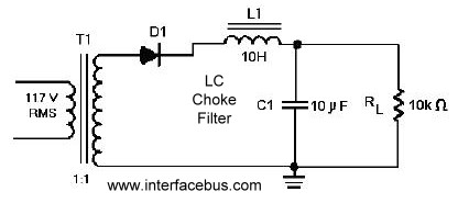
A circuit that utilizes one cycle of alternating current (AC) to produce direct current (DC). A half-wave rectifier circuit generates DC from either the positive or negative cycle of the AC input, but not both. It is important to...
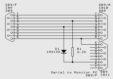
While the normal PC hardware might well run with just Tx, Rx and Ground connected, most driver software will wait forever for one of the handshaking lines to go to the correct level. Depending on the signal state it...
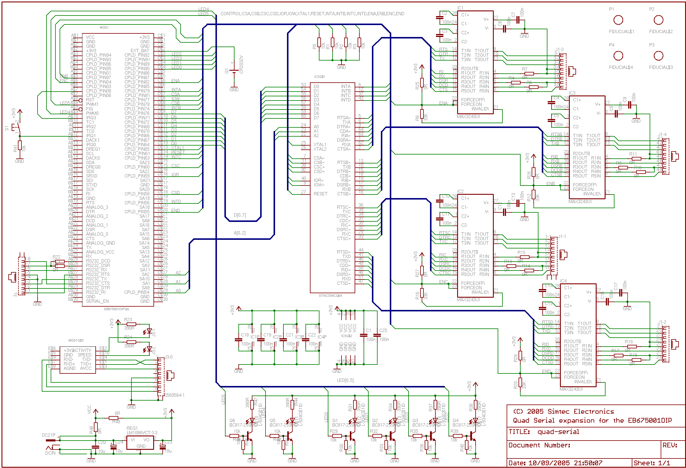
This application note details the integration of a quad serial controller into the EB675001 Module. A multi-source quad Universal Asynchronous Receiver and Transmitter (UART), specifically the 16554 type, was chosen to facilitate component sourcing and implementation. The RS232 line...
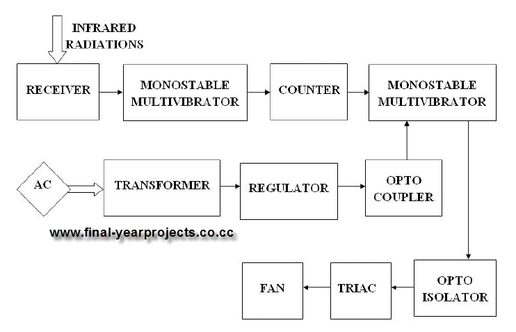
This report presents a comprehensive overview of a mini project titled "Remote Controlled Fan Regulator," developed in accordance with the curriculum requirements for the sixth semester of the Bachelor of Technology degree in Electrical and Electronics Engineering. The report...
The EN line is referred to as 'Enable'. This control line is utilized to indicate to the LCD that data is being sent. To transmit data to the LCD, the program must ensure that this line is low (0),...

The schematic for this tutorial is illustrated below and includes all necessary components for the tutorial to function. The PIC programming circuitry is not included, as it is assumed that the PIC is either programmed externally or that the...