
Contactless Live Line Detector

The live-line detector operates on the principle of capacitive coupling, which allows it to detect alternating current (AC) without direct electrical contact with the live conductor. The circuit typically consists of a capacitive sensor that is placed near the live wire, which picks up the electric field generated by the AC current flowing through the conductor.
In a standard configuration, the capacitive sensor is connected to an operational amplifier (op-amp) configured as a voltage follower or amplifier. The output of the op-amp can be fed into a microcontroller or a simple indicator light, such as an LED, to provide a visual indication of the presence of voltage.
The circuit may also include a resistor divider network to scale the detected voltage to a safe level for processing. It is important to incorporate safety features, such as isolation and over-voltage protection, to ensure that the circuit operates reliably without posing a risk to users or damaging components.
The design considerations for a live-line detector include sensitivity adjustments to ensure it can detect low voltages while avoiding false positives from nearby electrical devices. The layout of the circuit should minimize interference from other sources of electromagnetic fields, and the choice of components should reflect the desired operating frequency and environmental conditions.
In summary, a live-line detector provides a crucial function in electrical safety by enabling the detection of live conductors, thereby preventing accidental contact and enhancing safety protocols in electrical maintenance and inspection.Live-line detector is a circuit that detects the presence of a live mains conductor circuit operation: capacitive coupling between the live conductor and the.. 🔗 External reference
Related Circuits
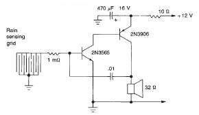
This rain detector electronic circuit project is a simple alarm circuit that activates an audio warning when liquid is detected on the sense pad. The circuit diagram is based on two transistors. When the sense pad conducts, transistors Tr1...

This circuit is designed to trigger on a 1 kHz tone. To change this frequency, refer to the table below, then change the resistor and capacitor values accordingly. More: all resistors are 5 or 10 percent tolerance, 1/4-watt; all...
The cooling is not only a PC using a small fan with an electronic commutator. A special feature of these fans is that their removal is less dependent on the load. Indicators monitoring the DC component of current may...
This circuit utilizes a complementary pair consisting of an npn metallic transistor T1 (BC109) and a pnp germanium transistor T2 (AC188) to detect heat. The circuit is designed to leverage the thermal sensitivity of the complementary transistor pair, where the...
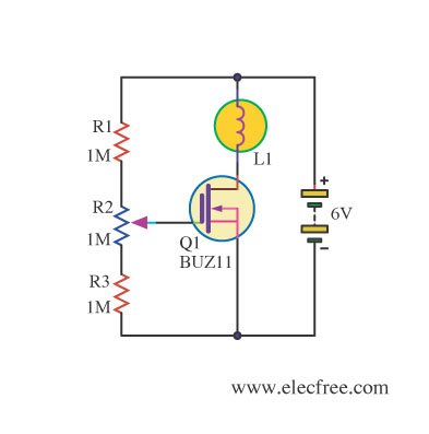
Changing the value of R2 alters the intensity of the lamp in this circuit, demonstrating the utility of a MOSFET as a variable resistor. An N-Channel Power MOSFET, designated as Q1, is utilized in the circuit. The specific part...

This homemade metal detector circuit will assist in locating objects made of materials with relatively high magnetic permeability. It is not suitable for detecting certain metals. This metal detector circuit operates on the principle of electromagnetic induction, utilizing a coil...