
Direction and speed control for series-wound motors

The circuit employs a bridge configuration of silicon controlled rectifiers (SCRs) Q1 to Q4, enabling efficient control over both the speed and direction of a series-wound DC motor. The series-wound motor is characterized by its field winding being connected in series with its armature winding, which allows for high torque at low speeds. The SCRs are activated in pairs, specifically in diagonal arrangements, which enables the motor to change its rotational direction based on the selected pair.
The operation begins with the user manipulating switch SI, which determines whether coupling transformer T1 or coupling transformer T2 is engaged with the pulsing circuit. This engagement is crucial as it dictates which diagonal pair of SCRs will be triggered. When SCRs Q2 and Q3 are activated, the field current flows in one direction, leading to a specific direction of rotation. Conversely, activating SCRs Q1 and Q4 reverses the field current, thus reversing the direction of rotation of the motor.
The armature current, which remains unidirectional, interacts with the reversed field current to produce the desired rotational effect. This characteristic of the series-wound DC motor makes it highly versatile for applications requiring variable speed and direction control.
The pulse circuit is integral to the operation, as it provides the necessary gate pulse to fire the SCRs. This pulse is generated from the energy stored in capacitor C1, which charges up when the circuit is idle and discharges to provide the required firing pulse when the switch is engaged. The timing and duration of the pulse can be adjusted to control the SCRs, thereby modulating the speed of the motor. The design ensures that the SCRs are only triggered when appropriate, preventing unwanted operation and ensuring safe, reliable motor control.
Overall, this circuit configuration exemplifies a robust method for controlling a series-wound DC motor's speed and direction, utilizing SCR technology for efficient power management and operational flexibility.The circuit shown here can be used to control the speed and direction of rotation of a series-wound dc motor. Silicon controlled rectifiers Q1-Q4, which are connected in a bridge arrangement, are triggered in diagonal pairs.
Which pair is turned on is controlled by switch SI since it connects either coupling transformer T1 or coupling transformer T2 to a pulsing circuit. The current in the field can be reversed by selecting either SCRs Q2 and Q3 for conduction, or SCRs Q1 and Q4 for conduction
Since the armature current is always in the same direction, the field current reverses in relation to the armature current, thus reversing the direction of rotation of the motor. A pulse circuit is used to drive the SCRs through either transformer T1 or T2. The pulse required to fire the SCR is obtained from the energy stored in capacitor Cl.
Related Circuits

This project shows you how to build a relay controller using the Basic Stamp I interfaced to the PC serial port. The Visual Basic 5 software developed for the interface lets you interact with the Basic Stamp to turn...
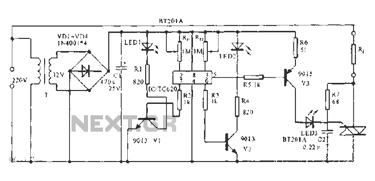
The built-in temperature sensor is utilized to control the triac TC620 for temperature regulation. The adjustment circuit, consisting of resistors Rp1 and Rn, allows for modifications to the lower temperature limit. When the ambient temperature exceeds this lower limit,...
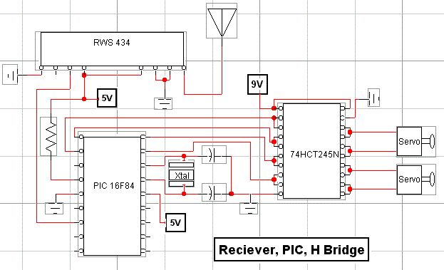
RF technology is an exciting field to incorporate into electronic designs. However, for beginners, constructing reliable RF transmitters and receivers can be challenging. RF (Radio Frequency) technology plays a crucial role in modern communication systems, enabling wireless data transmission over...

This document presents an infrared remote control tester circuit that can be constructed at a low cost. The circuit is built around the infrared receiver module TSOP1738. The state of the remote control can be observed through the sound...
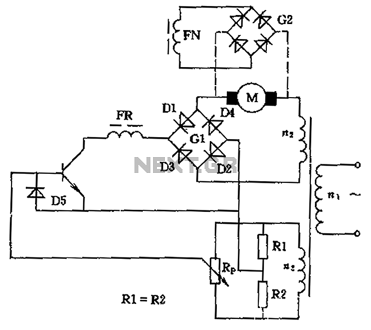
The circuit is designed to control the speed and direction of low-power DC motors, including series and shunt motors. It utilizes a rectifier bridge (G1) connected in series with the motor and linked to the secondary winding (n2) of...
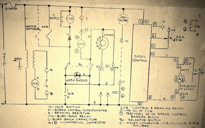
A Chemetron wire feeder is being utilized, and there is a desire to use the speed control from the control box to regulate the motor it originally contained. The Chemetron wire feeder is designed for efficient wire feeding in welding...