
contsant voltage current limited charger

The Constant Voltage Current Limited Charger power supply is designed to provide a stable output voltage while limiting the current to protect the connected load. This type of charger is particularly useful for applications where batteries or sensitive electronic components require a controlled charging environment to prevent damage from overcurrent conditions.
The circuit typically consists of a voltage regulation stage, which maintains a constant output voltage, and a current limiting mechanism that restricts the maximum output current. Common components used in this type of circuit include operational amplifiers, voltage reference diodes, and power transistors.
The operational amplifier is configured to compare the output voltage with a reference voltage. When the output voltage exceeds the set point, the operational amplifier adjusts the gate of a power transistor, reducing the output voltage to maintain the desired constant level. The current limiting feature is generally implemented using a shunt resistor in series with the load. A second operational amplifier monitors the voltage across this resistor; if it exceeds a predetermined threshold, the circuit will reduce the output voltage to limit the current flowing through the load.
This charger is suitable for various applications, including lead-acid, lithium-ion, and nickel-metal hydride batteries, ensuring safe and efficient charging while extending battery life. Proper heat dissipation measures, such as heat sinks or thermal cutoffs, should also be included in the design to prevent overheating of components during operation.
In summary, the Constant Voltage Current Limited Charger power supply is an essential component for safely charging batteries and sensitive electronic devices, ensuring that both voltage and current levels remain within specified limits.Constant Voltage Current Limited Charger power supply. Go to that page to read the explanation about above power supply related circuit diagram. 🔗 External reference
Related Circuits
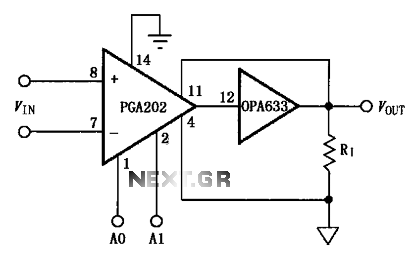
The figure illustrates a current boosting circuit configuration utilizing the PGA202 and OPA633 operational amplifiers. This circuit enhances the output current capability of the PGA202 operational amplifier, leveraging the performance characteristics of the OPA633 to achieve a higher output...
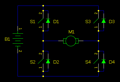
In motor control circuits, precautions must be taken to prevent the motor from feeding back into the power supply, which can cause the supply voltage to rise and potentially damage components. However, unless an external force is accelerating the...
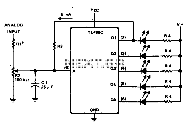
This circuit offers a visual representation of the input analog voltage level. It features a high input impedance at pin 8 and open-collector outputs that can sink up to 40 milliamperes. It is designed to drive a linear array...
All miniature electronic devices operate on batteries. Some require voltages higher than the standard battery voltages for efficient operation. When a battery of the specific voltage is unavailable, it becomes necessary to connect additional cells in series to increase...
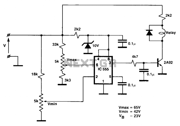
While the battery is charging, its voltage is measured at V. If the measured voltage is lower than the minimum threshold, the relay will be activated, connecting the charger circuit. When the battery voltage exceeds the maximum set point,...
This circuit diagram indicates when the input voltage deviates from two defined limits, V1 and V2. The limits are adjustable, and the circuit is designed to trigger the adjustable window. The supply voltage, Vcc, must be at least 2...