
Voltage detector relay

Additionally, if the voltage falls below a threshold known as VB (low breaking voltage), it is assumed that this low voltage indicates one or more damaged components in the battery. It is important to note that VB is significantly lower than the minimum set point.
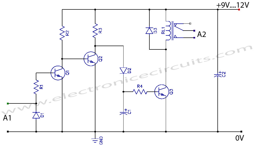
The described circuit involves a battery charging system that utilizes a relay for voltage management. The relay serves as a switch that connects or disconnects the charger based on the battery voltage readings. The operational thresholds are critical for ensuring battery health and preventing damage.
In this circuit, a voltage sensing mechanism continuously monitors the battery voltage. When the voltage is below the minimum threshold, the relay is energized, allowing current to flow from the charger to the battery, thereby initiating the charging process. The relay can be implemented using an electromagnetic coil that, when energized, closes the contacts to complete the charging circuit.
As the battery charges, the voltage is continuously monitored. Upon reaching the maximum set point, the relay is de-energized, breaking the connection between the charger and the battery. This feature is crucial for preventing overcharging, which can lead to battery damage or reduced lifespan.
Additionally, the circuit incorporates a low breaking voltage (VB) threshold. If the voltage drops below this level, it indicates potential issues within the battery, such as damaged cells or internal short circuits. This serves as a protective measure, prompting further inspection or maintenance of the battery system.
Overall, this circuit design effectively manages battery charging through precise voltage monitoring and relay control, ensuring optimal performance and safeguarding against potential battery failures.While the battery is being charged, its voltage is measured at V. If the measured voltage is lower than the minimum the relay will be energized, that wiU connect the charger circuit. When the battery voltage runs over the maximum set point, the relay is deenergized and it will be held that way until the voltage decreases below the minimum when it will be connected again.
The voltage is lower than a threshold VB (low breaking voltage) the relay will be assumed that such a low voltage is due to one or several damaged battery components. Of course VB is much lower than the minimum set point.
Related Circuits
This project presents a useful device for the beach, intended to deter individuals from touching personal belongings left on a towel while swimming. It can also be employed in an office or workshop setting. The circuit, compact in size...
The design is based on the TubeHobby and serves as the power supply used in their NC2. This kit was constructed as an initial project involving nixie tubes, and a review of this excellent kit can be found in...
VCR Camera Video Detector Switch Controller Circuit. This video detector switch controller circuit utilizes the video output from a VCR or camera to... This circuit functions as a video detector switch controller, designed to manage the video output from a...
A circuit is required where, upon power application, a timer triggers, keeping a relay in the off state. Once the timer completes its cycle, the relay will activate. The circuit design consists of a timer integrated with a relay to...
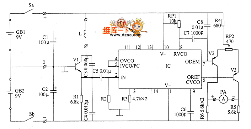
The metal detector circuit comprises several key components, including a power circuit, a sine wave oscillator, a PLL (phase-locked loop) circuit, and a hybrid amplifying circuit. The power circuit is made up of batteries GBI and GB2, filter capacitors...
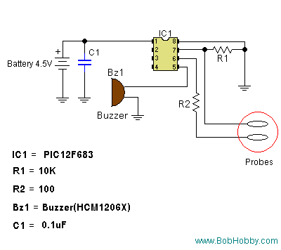
The following circuit illustrates a Water Level Detector Circuit Diagram. This circuit is based on the PIC12F683 microcontroller. Features include the ability of the PIC microcontroller to enter a sleep mode. The Water Level Detector Circuit utilizing the PIC12F683 microcontroller...