
Five-step voltage-level indicator

The circuit utilizes a high-impedance operational amplifier configured as a voltage follower to ensure minimal loading on the input signal. The output from the op-amp feeds into a comparator circuit, which compares the input voltage against predefined reference levels corresponding to each LED in the array. The reference voltages can be set using a resistor divider network connected to a stable reference voltage source.
When the input voltage reaches specific thresholds, the comparator outputs transition, activating the open-collector outputs. These outputs are connected to the anodes of the LEDs, while the cathodes are tied to ground through current-limiting resistors. This configuration allows the circuit to illuminate the appropriate number of LEDs based on the input voltage level, providing a clear visual indication.
To ensure the circuit operates correctly, it is crucial to maintain the input voltage within the specified range. If the input voltage exceeds eight volts, it may lead to undesired behavior or damage to the components. Therefore, voltage clamping devices such as Zener diodes may be incorporated to protect the input stage from overvoltage conditions.
In summary, this circuit effectively visualizes analog voltage levels through a straightforward LED array, combining high input impedance, open-collector outputs, and adjustable reference voltages to create an intuitive and informative display.This circuit provides a visual indication of the input analog voltage level. It has a high input impedance at pin 8 and open-collector outputs capable of sinking up to 40 milliam-peres. It is suitable for driving a linear array of 5 LEDs to indicate the level is 5 steps The voltage at the analog input should be in the range of zero to approximately one volt and should never exceed eight volts.
Related Circuits
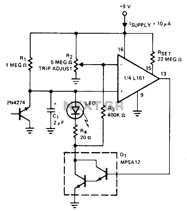
The indicator flashes an LED when the battery voltage drops below a certain threshold. The 2N4274 emitter-base junction serves as a zener diode, establishing approximately 6V on the L161's positive input. As the battery voltage decreases, the output of...
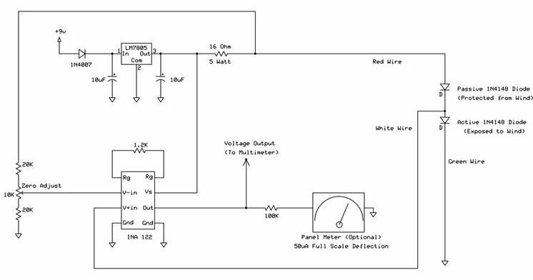
The following circuit illustrates a wind speed indicator circuit. It operates with a constant 5 VDC output provided by the LM7805 voltage regulator, using a 9 VDC supply. The wind speed indicator circuit is designed to measure and display wind...
Detects clipping in preamp stages, mixers, amplifiers, etc. Single LED display powered by a 9V battery. This circuit is intended for use as a standalone unit. The clipping detection circuit is designed to monitor audio signals in various electronic devices...
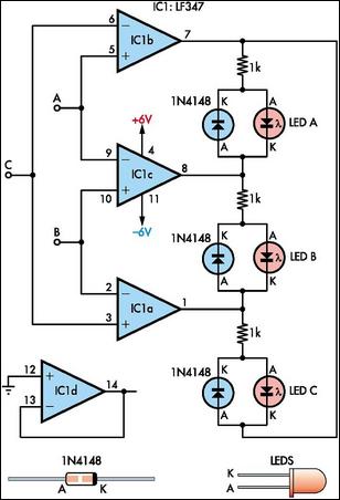
This circuit indicates which of three voltages, ranging from approximately -4V to +4V at points A, B, and C, is the highest by illuminating one of three indicator LEDs. Alternatively, it can be configured to indicate the lowest of...

This circuit indicates which of three voltages, ranging from approximately -4V to +4V at points A, B, and C, is the highest by illuminating one of three indicator LEDs. It can also be configured to indicate the lowest of...

The circuit is a simple RF-actuated switch that responds to any strong electromagnetic field in the vicinity of the pickup wire. The length of the wire will depend on the required coupling, but a 250 mm length wrapped around...