
Cuckoo Sound Generator Circuit Schematic

The Cuckoo Sound Generator Circuit is designed to produce a distinctive two-tone sound reminiscent of a cuckoo's call. This circuit is particularly suitable for applications such as doorbells, where an engaging audio signal can enhance user experience. The key components of this circuit include an oscillator, an audio amplifier, and a loudspeaker.
The oscillator is responsible for generating the two distinct tones that characterize the cuckoo sound. Typically, this can be achieved using a 555 timer IC configured in astable mode, which produces a square wave output. By adjusting the resistor and capacitor values in the circuit, the frequency of oscillation can be fine-tuned to create the desired tone variations.
The audio amplifier is integrated into the circuit to boost the output signal from the oscillator, ensuring that the sound produced is loud enough to be heard clearly. A common choice for the amplifier stage is a small audio amplifier IC, such as the LM386, which provides sufficient power to drive a small loudspeaker effectively.
The loudspeaker is the final component in the circuit, converting the amplified electrical signals into audible sound. The selection of the loudspeaker should be based on the required volume and sound quality for the intended application.
Overall, this circuit combines simplicity and functionality, making it an ideal choice for generating entertaining sound effects in various electronic projects. Properly assembling the components according to the schematic will yield a reliable cuckoo sound generator suitable for a range of uses.Cuckoo Sound Generator Circuit Schematic Circuit This circuit generates a two-tone effect very much alike the cuckoo song. It can be used for door-bells or other purposes thanks to a built-in audio amplifier and loudspeaker.
Use.. 🔗 External reference
Related Circuits
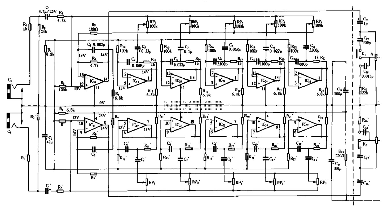
Figure 1-98 illustrates a double five-band equalizer circuit featuring a secondary connection. In this configuration, IC1 and IC14 serve as voltage amplifiers for each channel of the equalizer. The circuit also includes IC11, IC24, IC2, IC34, IC31, IC12, IC23,...
The protected section of track can be of any desired length and does not need to be equal on both sides of the crossing. The circuit operates bidirectionally and can be linked with other grade crossing circuits to provide...
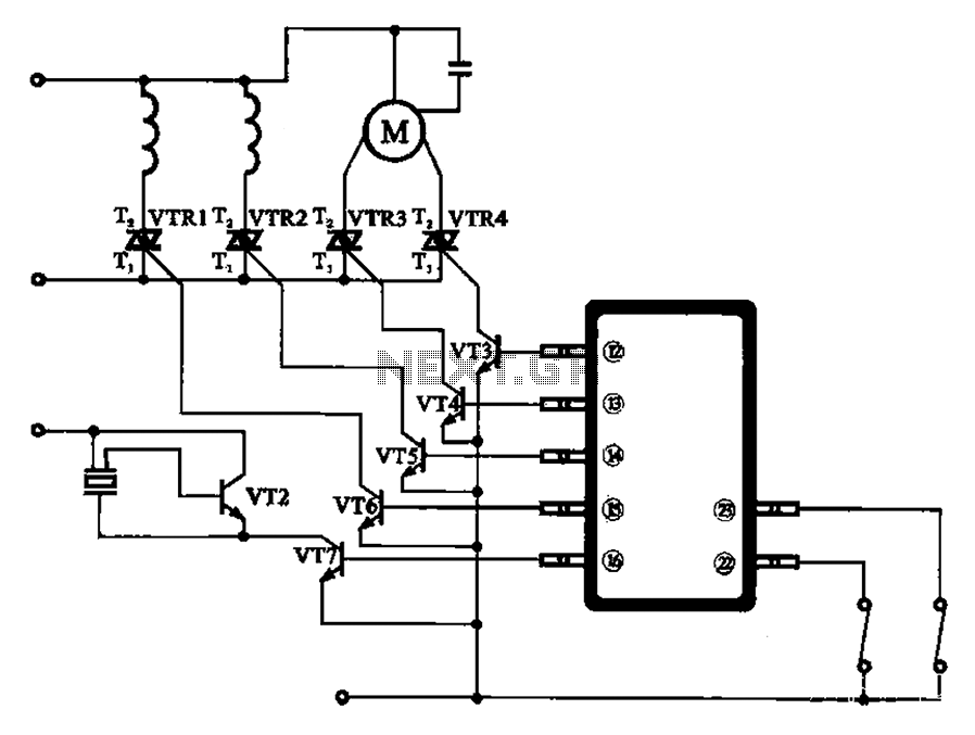
The schematic for the automatic washing machine motor driver outlines the motor drive circuit for the Narcissus XQB30-III-type washing machine. The control circuit comprises four Triacs, four drive transistors, and a control chip. This setup allows for the activation...
This is an audio power amplifier that delivers 40 W at 8 ohms in Class A operation. The power transistors are continuously active, enabling a substantial current to flow. The audio power amplifier described operates in Class A mode, which...
The light from a flashlight is directed at a phototube, which activates a CMOS logic circuit powered by a battery. This circuit controls the switching action to turn the motor of a model train or other electric toys on...
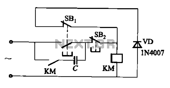
An AC contactor switch, when used with DC or pulse DC excitation, can minimize short circuit and core power consumption. This results in a significant reduction in the power consumption of the electromagnet, which can eliminate noise and reduce...