
Current Source

This circuit effectively demonstrates the implementation of a low-current source using readily available components, making it suitable for applications that require precise current regulation. The choice of the CA3130 operational amplifier is significant due to its low input bias current, which is crucial for maintaining accuracy in low-current applications. The operational amplifier’s configuration as a voltage follower ensures that the output voltage closely follows the input voltage, thereby allowing for precise control over the current flowing through R2.
The PMOS transistor selected from the CD4007A is advantageous due to its integrated nature, reducing the need for additional discrete components. This integration minimizes the circuit's footprint and simplifies the design process. The operational amplifier's output must reach a level sufficient to turn off the internal FET of the CD4007A, necessitating the 5 V supply voltage. This requirement ensures that the circuit operates efficiently within its desired parameters.
The output voltage range of 0 to 3 V is particularly useful in applications requiring low current levels, such as sensor biasing or precision analog signal processing. The resistor RI serves as a critical component in controlling the output current, providing flexibility in adjusting the current output as needed. Overall, this circuit design exemplifies an efficient approach to creating a low-current source suitable for various electronic applications. This circuit uses readily available parts to implement a 0-to-200-nA current source. The circuit borrows a PMOS transistor from the input stage of a DC4007A, which is easier to obtain than a discrete PMOS transistor. The CA3130 op amp operates as a follower so that its positive input sets the current that flows through R2.
The MOSFET input stage of this op amp exhibits low-input current. The op amp must be able to produce an output voltage high enough to turn the CD4007A"s internal FET off. Thus, the op amp requires a positive supply voltage of 5 V. The circuit presents an output voltage from 0 to 3 V, and RI controls the amount of output current.
Related Circuits
An operational amplifier circuit can provide a constant voltage source with a high amplification factor and substantial load current. Even with significant variations in circuit parameters, the output voltage maintains high precision. The output current limit is managed by...
This application note details the design of a 50-watt, isolated, forward converter, utilizing the MAX8540 synchronizable, high-frequency, current-mode PWM controller. The schematic design of the 50-watt isolated forward converter using the MAX8540 involves several key components and stages to ensure...
A current regulator functions as a load when connected to a voltage source or in series between a voltage source and an actual load. The primary characteristic of a current regulator is to maintain a constant current output regardless...
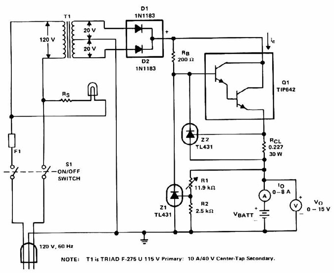
Lead Acid Battery Charger with current limit power supply. Refer to the specified page for an explanation of the related circuit diagram. The lead-acid battery charger with a current limit power supply is designed to safely charge lead-acid batteries while...
The BC547 transistor has a maximum operating current of 100 mA and a maximum voltage rating of 65 volts. When oriented with the label facing the viewer, the three terminals from left to right are collector, base, and emitter....
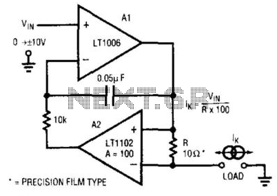
This circuit is a programmable current source that utilizes the LT1102 operational amplifier from Linear Technology Corp. in conjunction with the LT1006 operational amplifier. The first amplifier (A1), biased by a voltage source, drives current through a resistor (R)...