
Dark-activated 230V Lamp

The described circuit functions as an automatic lighting control system that activates lamps at dusk and deactivates them at dawn. The core components include two transistors (Q1 and Q2), a silicon-controlled rectifier (SCR), a photoresistor (R1), a resistor (R2), and a capacitor (C1).
Q1 and Q2 are configured to operate as a trigger circuit for the SCR, which is the primary switching device responsible for controlling the power to the lamps. The transistors are likely arranged in a Darlington pair configuration to amplify the signal from the photoresistor. This arrangement ensures that even a small change in light detected by R1 can result in a significant change in the output, allowing the SCR to turn on or off effectively.
The frequency of operation is set at 100Hz, which is determined by the values of R2 and C1. The pulse duration, which is the time the SCR remains in the conducting state, is also influenced by these components. R2 is a current-limiting resistor that works in conjunction with C1, a timing capacitor. The charging and discharging of C1 through R2 dictate the timing characteristics of the circuit.
R1, being a photoresistor, plays a critical role in sensing ambient light levels. During daylight, R1 exhibits low resistance, which effectively shorts C1, preventing it from charging and thus inhibiting the operation of the circuit. Conversely, in low-light conditions, R1's resistance increases significantly, allowing C1 to charge and enabling the circuit to function. This change in resistance is the key mechanism that triggers the SCR, allowing the connected lamps to illuminate.
Overall, this circuit serves as an efficient solution for automatic lighting control, utilizing basic electronic components to achieve reliable performance in response to changing light conditions. The design is suitable for outdoor lighting applications, such as garden lights or street lamps, where automatic operation enhances convenience and energy efficiency.This device allows one or more lamps to illuminate at sunset and turn off at dawn. Q1 and Q2 form a trigger device for the SCR, providing short pulses at 100Hz frequency. Pulse duration is set by R2 and C1. When the light hits R1, the photo resistor assumes a very low resistance value, almost shorting C1 and preventing circuit operation. When R1 is in the dark, its resistance value becomes very high thus enabling circuit operation. 🔗 External reference
Related Circuits
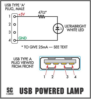
The device is referred to as the Itsy Bitsy USB Lamp. This concept is remarkably straightforward, raising the question of why it had not been conceived earlier. Originating as a student project at Massey University in Wellington, New Zealand,...
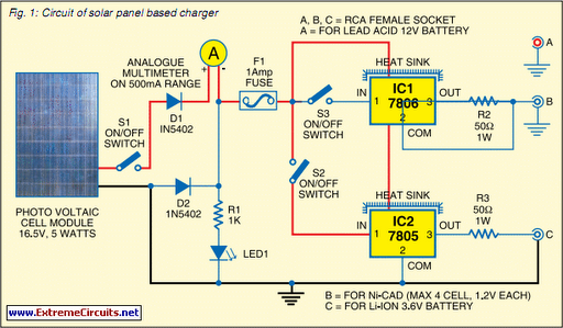
Savings on electricity bills can be achieved by utilizing alternative power sources. The photovoltaic module, or solar panel, described here has a power output of 5 watts and delivers 16.5V under full sunlight conditions, with a current output of...
This circuit is similar to the LED clock using 12 neon indicator lamps instead of LEDs. It operates from 2 high capacity ni-cad cells (2.5 volts) which keep it going for a couple weeks. High voltage (70 volts) for...

This design is likely to generate significant radio frequency interference (RFI) without the incorporation of a choke. The house wiring serves to limit the rate of change of current (di/dt). It is a cost-effective design that demonstrates hysteresis at...
This ultra-bright white LED lamp operates on 230V AC with low power consumption. It is suitable for illuminating VU meters, SWR meters, and similar applications. The cost of ultra-bright LEDs available in the market ranges from Rs 8 to...
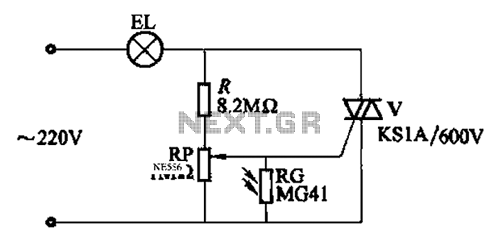
An automatic light control circuit is designed to illuminate a lamp when it is dark and to turn off the light at daybreak. The circuit, as shown in Figure 2-86, employs bidirectional thyristor tubes and features a straightforward design....