
Logic State Indicator

The circuit for the logic state indicator primarily consists of a digital IC output, a bicolor LED, and a current-limiting resistor. The digital IC output provides a binary signal, which can be either high (logic 1) or low (logic 0).
When the output from the IC is high, the current flows through the circuit, energizing the bicolor LED and causing it to emit green light. This is achieved by connecting the anode of the green segment of the bicolor LED to the output pin of the digital IC. The cathode of the green segment is connected to ground through a resistor, which limits the current flowing through the LED to a safe level, preventing damage.
Conversely, when the output is low, the bicolor LED does not light up, indicating a logic state of 0. The circuit can be powered using a standard voltage supply compatible with the digital IC, typically ranging from 3.3V to 5V, depending on the specifications of the IC used.
This simple yet effective logic state indicator is useful for troubleshooting digital circuits, allowing engineers and technicians to quickly ascertain the output state of an IC without the need for complex test equipment. The use of a bicolor LED enhances visibility and provides immediate feedback on the logic state.Here is a simple logic state indicator to test whether the output of digital IC is in logic 1 or 0. The Bicolor LED lights Green when the logic state is 1.. 🔗 External reference
Related Circuits
This review highlights a dual-test scenario involving the FVP preamp, with initial contacts made with Vacuum State and insights provided by Geoff during a trip to Brittany. The FVP was sent to France for evaluation. Geoff tested the FVP5A...
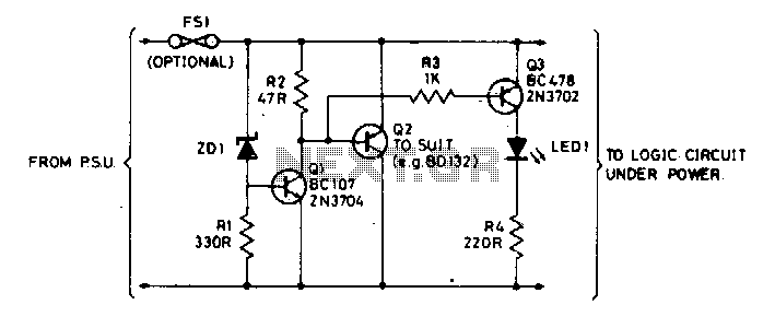
The Zener diode ZD1 monitors the supply voltage, and if the supply exceeds 6 V, transistor Q1 will activate. This activation causes transistor Q2 to conduct, thereby clamping the voltage rail. The subsequent behavior of the circuit is contingent...

Connect with Cadence technologists and peers in the Cadence Community. Stay informed about technology trends, news, and opinions through blogs, forums, and social networking. The Cadence Community serves as a collaborative platform for professionals in the electronics design automation (EDA)...
This logic probe utilizes a single CMOS integrated circuit (IC) to indicate three logic states: High, Low, and Pulsing. If the probe input is in a high impedance state, which occurs when it is not connected to a circuit,...

When testing circuits with a logic probe, it can be challenging to observe the LEDs on the probe to ascertain the logic state. This probe offers an audible indication of the logic states. It is specifically designed for TTL...
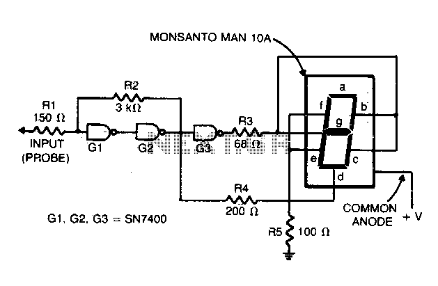
Gates G1 and G2, along with resistors R1 and R2, create a straightforward voltage monitor with a trip point set at 1 volt. Gate G3 functions as an inverter. The display section of the tester features a common anode...