
DC-AC Inverter Convert 12V DC Voltage to 110/220V AC Voltage

The described DC to AC inverter circuit employs a basic square wave generation technique, which is effective for a range of applications despite its simplicity. The configuration utilizes a bridge of MOSFETs that alternates the direction of current through the primary winding of the transformer, thus generating an alternating current (AC) output from a direct current (DC) source.
The transformer plays a crucial role in stepping up the voltage to the desired level while also isolating the load from the power source for safety. It is essential that the transformer is rated to handle the maximum current of 10 Amps to prevent overheating or damage during operation. The selection of the transformer should consider both the current rating and the power rating, ensuring it can handle loads up to 120 Watts efficiently.
In practical applications, this inverter circuit can be used to power various electronic devices, including small appliances, lights, and other equipment that operates on AC voltage. The square wave output may not be suitable for devices that require a pure sine wave for optimal performance; however, it is adequate for resistive loads and many inductive loads.
It is also important to incorporate adequate heat sinking for the MOSFETs to manage thermal performance, especially under maximum load conditions. Additionally, implementing filtering capacitors at the output can help reduce voltage spikes and improve the quality of the AC waveform, making it more suitable for sensitive electronic devices. Overall, this inverter circuit exemplifies a cost-effective solution for converting DC to AC power for various applications.The DC to AC inverter circuit shown in the schematic here is very simple circuit since it produce square wave, but it`s enough to power many devices. Here is the schematic diagram of the inverter circuit: The MOSFET is configured as bridge, so the current will flow alternatively in through the primary windings of the transformer.
The most expensiv e part of this dc-ac inverter circuit is the transformer, since it must handle high current up to 10 Amps. You can power any device up to 120 Watts using this 12V inverter circuit. 🔗 External reference
Related Circuits
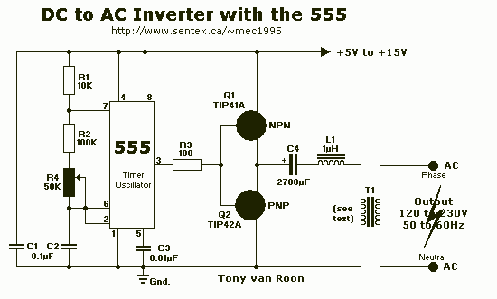
This DC-to-AC inverter schematic produces an AC output at line frequency and voltage. The 555 is configured as a low-frequency oscillator, tunable over the frequency range of 50 to 60 Hz by Frequency potentiometer R4. The 555 feeds its...

In this circuit, an LM339 quad voltage comparator is utilized to generate a time delay and control a high current output at low voltage. Approximately 5 amps of current can be sourced using a pair of fresh alkaline D...
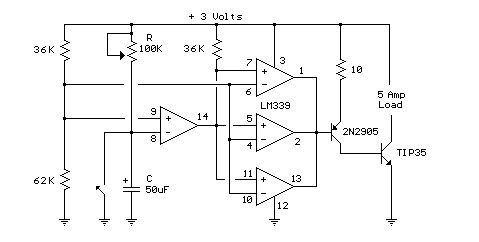
This circuit utilizes an LM339 quad voltage comparator to create a time delay and manage a high current output at low voltage levels. Approximately 5 amps of current can be achieved using two fresh alkaline D batteries. Three of...
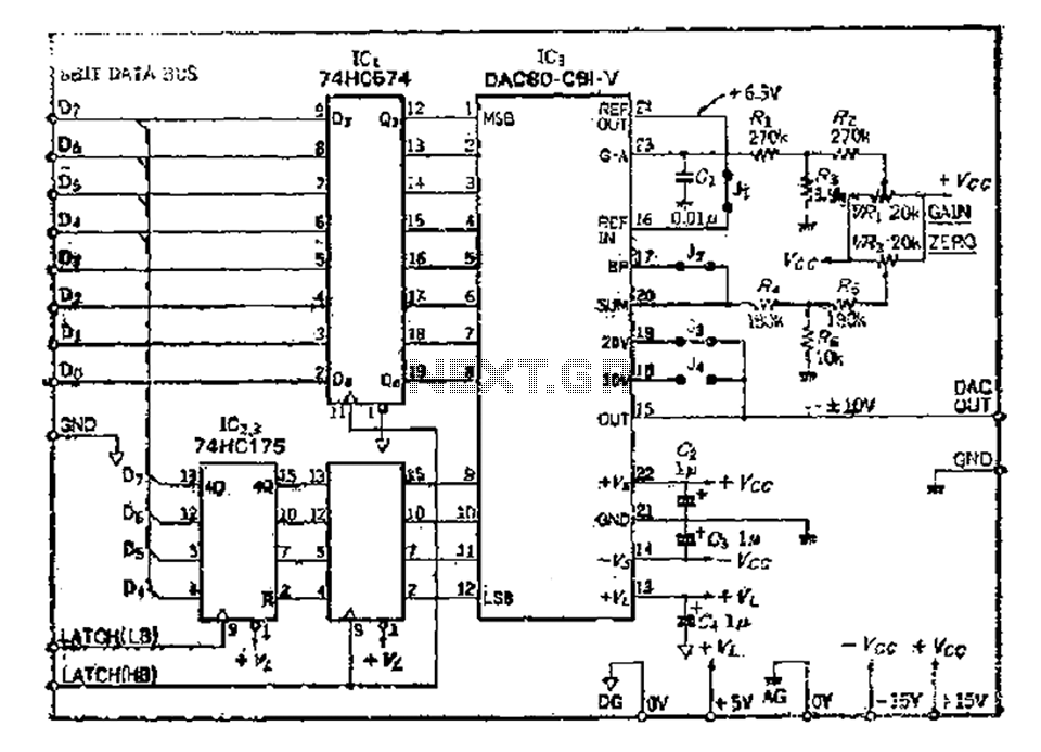
The 8 microcomputer data operates with an 8-bit parallel output, while also accommodating serial input for D-A converters. Typically, data must be entered in two groups and processed as a whole. The requirements for data latching involve 16 straight...
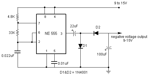
Opamps are very useful. But one of their major drawbacks is the requirement of a dual supply. This seriously limits their applications in fields where a dual supply is not affordable or not practicable. This circuit solves the problem...
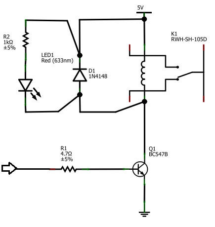
The BC547B transistor has a collector-base voltage (Vcbo) of 50V, a collector-emitter voltage (Vceo) of 45V, and an emitter-base voltage (Vebo) of 6V. In contrast, the BC548 transistor in the original circuit has a Vcbo of 30V, a Vceo...