
DC Motor Controller using Transistor TIP31

The described DC motor controller circuit utilizes an H-Bridge configuration to control the direction and speed of a DC motor. The TIP31 transistor, which is a power transistor, is employed in the circuit to handle the current required by the motor. The H-Bridge configuration allows for bidirectional control of the motor, enabling it to rotate in either direction based on the state of the control switches.
In this circuit, the switches S1 and S2 function as user inputs. When either switch is pressed, it closes the circuit and activates the corresponding leg of the H-Bridge, allowing current to flow through the motor in one direction or the other. If S1 is pressed, the motor will rotate in one direction, while pressing S2 will reverse the motor's rotation. The normally open configuration of these switches ensures that the motor remains off until the user actively engages one of the switches.
The inclusion of an LED indicator is a critical feature of this design. This LED visually signals the current direction of the motor's rotation. For instance, if the motor is set to rotate clockwise, the LED may light up in one color, while a counterclockwise rotation could trigger the LED to change to another color or turn off, depending on the specific design choices made in the circuit.
Overall, this DC motor controller circuit is a practical and efficient solution for applications requiring precise control of motor direction and operation, such as in robotics, automation systems, or remote-controlled devices. The simplicity of using a TIP31 transistor in conjunction with push-button switches makes this circuit accessible for both educational purposes and practical implementations.This is a DC motor controller circuit, built using transistor TIP31 based on H-Bridge concept. The switch S1 and S2 are normally open, push to close, press button switches. The LED function is to indicate the direction of motor rotation, y.. 🔗 External reference
Related Circuits
This circuit diagram for a 12V inverter is straightforward to construct, utilizing inexpensive components that many electronics hobbyists may already possess. While it is feasible to design a more powerful circuit, the complexity associated with handling high currents on...
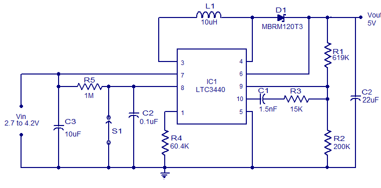
A simple 5V boost converter utilizing the LTC3440 is presented. The LTC3440 is a high-efficiency DC to DC converter capable of operating with input voltages that are below, above, or equal to the output voltage. With synchronous rectification, the...
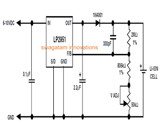
Unlike lead-acid batteries, one advantage of lithium-ion (Li-Ion) batteries is that they can be charged at a 1C rate initially. This means the charging current can be as high as the rated ampere-hour (AH) capacity of the battery at...
The servo motor has numerous applications in various fields, including robotics, puppetry, photography, and more. These compact motors can accurately position their output shaft to any specified angle and maintain that position. Most servos have a motion range of...
As summer approaches, many individuals focus on staying cool during hot days. For some, this means turning on the air conditioner and enjoying a cold beverage. However, it is essential to consider how to maintain the temperature of radio...
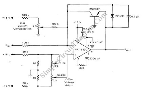
This low-cost logarithmic converter is constructed using an operational amplifier (op-amp) and a transistor. The circuit utilizes a Motorola MC1539G op-amp connected to a PNP transistor. The logarithmic converter circuit is designed to convert linear input signals into logarithmic output...