
DC Servo MOSFET Amplifier

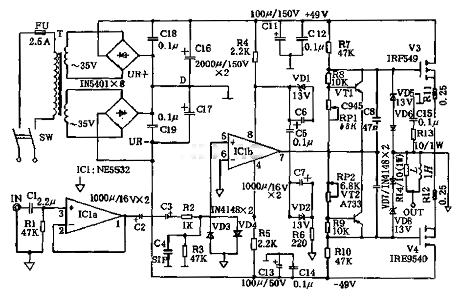
The Apex amplifier circuit is designed to deliver high-fidelity audio amplification. The schematic incorporates a variety of resistor values for R14, allowing for tuning of the amplifier's response and performance. The choice of resistor value affects the gain, bandwidth, and overall stability of the amplifier.
In the circuit, R14 plays a crucial role in determining the feedback network's characteristics, which directly influences the amplifier's linearity and distortion levels. By experimenting with resistor values of 22k, 30k, and 56k, users can observe how these changes impact the amplifier's output characteristics, such as frequency response and gain.
The power supply configuration is another critical aspect of the amplifier's design. Different supply voltages can significantly alter the performance, affecting parameters like headroom, dynamic range, and maximum output power. It is essential to ensure that the power supply meets the voltage and current specifications required by the amplifier to avoid issues like clipping or thermal overload.
When constructing the Apex amplifier, careful attention should be paid to the layout of the circuit to minimize noise and interference. Proper grounding techniques and the use of decoupling capacitors can further enhance the performance of the amplifier. Overall, the flexibility in resistor values and supply configurations allows for a customized approach to achieving the desired audio quality.Apex seems i begin to love this amp the corrected clear schematic is this with different R14 values(tried 22k,30k,56k) and different supply.. 🔗 External reference
Related Circuits
A popular project among microcontroller enthusiasts is to build a radio-controlled clock. Tiny receiver boards are available, equipped with a pre-tuned ferrite antenna that receives and demodulates the DCF77 time signal broadcast from Mainflingen in Germany. DCF77 has an...
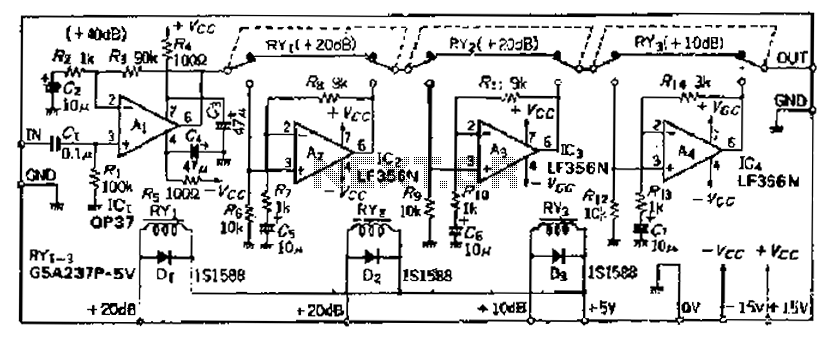
Although the basic amplifier circuit phase AC amplifier remains unchanged, the selection of the correct gain requires the use of series resistors. The circuit does not include a 9kΩ resistor. The input amplifier Ai selected is the OP37, which...
This is a diagram of a car audio active loudspeaker utilizing the LF353 operational amplifier from National Semiconductor. For optimal performance, the NE5532 is recommended to split the audio signal into three frequency bands using an active filter. The...
The TMB-1 is an RF amplifier unit and receiving accessory compatible with low-impedance broadband loops, high-impedance terminated loops (such as Pennant, Flag, or Kaz Delta), and whip (telescoping rod) antennas. This design is optimized for operation within the frequency...
The amplifier circuit presented in this paper introduces a floating power supply aimed at increasing output power. The output power of the amplifier is influenced primarily by the final stage amplifier supply voltage. The circuit's principle is illustrated in...
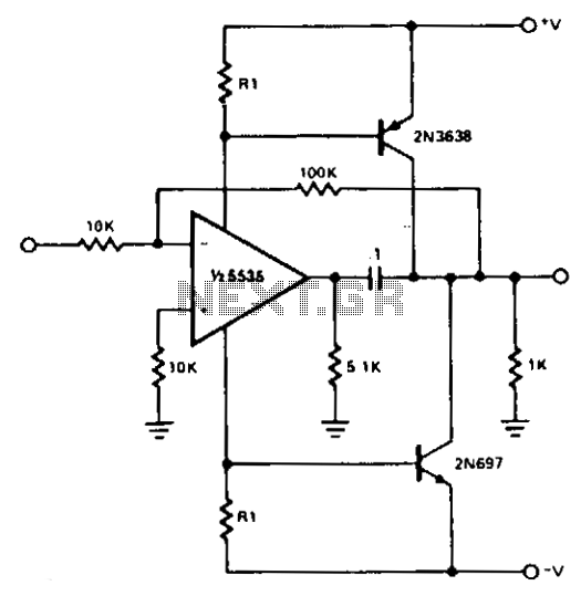
For most applications, the power provided by operational amplifiers (op amps) is adequate. However, there are instances where a greater power handling capability is required. A straightforward power booster that can drive moderate loads utilizes the NE5535 device. Other...