
DCF77 Preamplifier

The radio-controlled clock project utilizes a microcontroller to decode the DCF77 time signal, which is transmitted at a frequency of 77.5 kHz. The receiver module typically incorporates a ferrite antenna that captures the signal, but in areas where reception is weak, the design can be enhanced with a preamplifier. The preamplifier stage is critical for improving the signal quality before it reaches the microcontroller.
The preamplifier design includes a source follower transistor (T1) that ensures minimal loading on the antenna, preserving the quality of the received signal. Following this, a bipolar transistor (T2) is employed to amplify the signal by approximately 5 dB, which is essential for maintaining signal integrity when interfacing with the DCF77 module.
To couple the amplified signal to the DCF77 module, a transformer is used. The secondary side of this transformer, along with capacitors C4 and C5, creates a resonant circuit that must be accurately tuned to resonate at the DCF77 carrier frequency. Proper tuning is achieved using an oscilloscope to monitor the output signal amplitude while adjusting the trimmer capacitor (C5). The use of a signal generator to inject a known sine wave into the circuit allows for precise tuning, ensuring optimal performance of the receiver system.
The choice of transformer is significant; it must be designed to operate effectively at the resonant frequency of 77.5 kHz. The prototype's use of the FT50-77 core, with its specific winding configuration, illustrates a practical implementation. For further flexibility, transformers with adjustable cores can be utilized, allowing for fine-tuning of the resonant frequency without the need for additional trimmer capacitors. This detailed approach to designing the radio-controlled clock ensures that it can achieve reliable timekeeping even in less-than-ideal reception conditions.A popular project among microcontroller aficionados is to build a radio-controlled clock. Tiny receiver boards are available, with a pre-adjusted ferrite antenna, that receive and demodulate the DCF77 time signal broadcast from Mainf lingen in Germany. DCF77 has a range of about 1, 000 miles. All the microcontroller need do is decode the signal and output the results on a display. The reception quality achieved by these ready-made boards tends to be proportional to their price. In areas of marginal reception a higher quality receiver is needed, and a small selective preamplifier stage will usually improve the situation further. The original ferrite antenna is desoldered from the receiver module and connected to the input of the preamplifier.
This input consists of a source follower (T1) which has very little damping effect on the resonant circuit. A bipolar transistor (T2) provides a gain of around 5 dB. The output signal is coupled to the antenna input of the DCF77 module via a transformer. The secondary of the transformer, in conjunction with capacitors C4 and C5, forms a resonant circuit which must be adjusted so that it is centered on the carrier frequency.
An oscilloscope is needed for this adjustment, and a signal generator, set to generate a 77. 5 kHz sine wave, is also very useful. This signal is fed, at an amplitude of a few milli-volts, into the antenna input. With the oscilloscope connected across C4 and C5 to monitor the signal on the output resonant circuit, trimmer C5 is adjusted until maximum amplitude is observed. It is essential that the transformer used is suitable for constructing a resonant circuit at the carrier frequency.
Our proto-type used a FT50-77 core from Amidon on which we made two 57-turn windings. It is also possible to trim the resonant frequency of the circuit by using a transformer whose core can be adjusted in and out. In this case, of course, the trimmer capacitor can be dispensed with. 🔗 External reference
Related Circuits
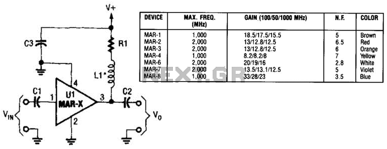
In this basic MAR-x-based circuit, both the input and output consist of a single DC-blocking capacitor (C1 for the input and C2 for the output, respectively). The DC power supply network, which includes L1 and R1, is connected to...
The three circuits were based on the vacuum tube ECC83, designed to produce phono preamplifiers in compliance with RIAA standards. The described circuits utilize the ECC83 vacuum tube, a dual-triode component known for its low noise and high gain characteristics,...
The concept of an AC model for the triode is presented, and the equivalent circuit technique is described. Theoretical calculations for amplifier gain and frequency response are derived and compared to simulation results in the SPICE3 environment, showing good...
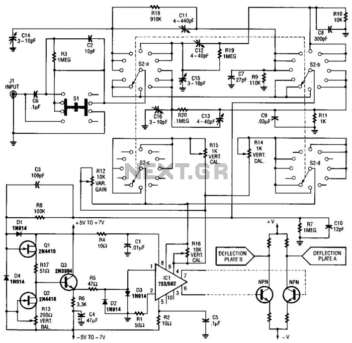
An oscilloscope front-end amplifier can be constructed using low-cost transistors and video amplifier integrated circuits (ICs). This preamplifier utilizes a FET input along with compensated attenuators, achieving an approximate bandwidth of 100 MHz, which is sufficient for most general-purpose...
Both transistors should be low-noise types. In the original circuit, BC650C was used, which is an ultra-low noise device. These transistors are now difficult to find, but BC549C or BC109C are good replacements. The circuit is self-stabilizing and will...

This circuit exhibits an exceptionally fast high-frequency response, as demonstrated by applying a 100 kHz square wave to the input. All graphs were produced using Tina Pro. The circuit's design is optimized for high-frequency applications, showcasing rapid response times that...