
Telephone Line optical and sound Ring

The circuit described functions as a telephone ring indicator, providing both audio and visual alerts when a call is received. It operates by converting the ringing signal from the telephone line into a 400 Hz pulse signal, which is processed by various integrated circuits and components to generate the desired outputs.
The heart of the circuit is the LM555 timer (IC2), which is configured to detect the ringing signal on the telephone line. When a call is received, the LM555 generates a pulse at its output (pin 3). This pulse is then amplified by the TL071 operational amplifier (IC4), which boosts the signal strength to drive a speaker or buzzer, allowing the user to hear the ring at a customizable volume. The volume is adjustable through the trimmer potentiometer (TR1), which can be replaced with a standard potentiometer for more precise control.
In addition to audio output, the circuit features an LED (LD1) that provides a visual indication of the ringing signal. The LED lights up in response to the ringing, serving as an additional alert method.
The circuit also includes an interface for controlling external devices through IC3, allowing for further customization according to specific user needs or preferences. This could involve activating other alert systems or integrating with home automation systems.
The part list includes various resistors, capacitors, and diodes that support the operation of the circuit. Notably, the use of a Zener diode (D1-2) ensures voltage regulation, protecting sensitive components from voltage spikes. The connectors (CON1 and CON2) facilitate easy integration with other systems or components.
Overall, this circuit provides a reliable solution for alerting users to incoming telephone calls, combining both auditory and visual cues in a straightforward design.It is a relatively simple circuit, with which we can have optical and sound clue, when we have telephone ring in the line of telephone. The calls in the line, are changed in pulses of frequency 400 HZ from the IC2, in exit 3. Then via the IC4, after they are strengthened at two times, they can be drive to the entry of amplifier and a loudspeaker, so that we hear the ring, in what level we want.
The desirable level of sound is regulated by the trimmer TR1 that if we want can be replaced with pontesometer. With the led LD1 we have optical clue, of rings. Simultaneously via the IC3 it can become control, exterior circuit, adapted in the needs each virtuous.
Part List R1-3-13=4.7Kohm C1-7 =100nF 630V Q1-2 = BC550C R2-11-12 =1Mohm C2=4.7nF 63V MKT IC1-3 =4N35 - CNX38 R4 =1Kohm C3 =220uF 25V IC2=LM555 R5 = 2.2Kohm C4 =33nF 63V MKT IC4 =TL071 R6 = 33Kohm C5 =220nF 63V MKT LD1 =LED 3-5 mm R7 =390Kohm C6 =10uF 25V TR1=10Kohm Trimmer or Pont. R8 =820ohm C8 =47nF 63V MKT CON1 =4 pin connector R9 =22Kohm C9 =100uF 25V CON2 =4 pin connector R10 =1.8Kohm D1-2 =20V 1,3W Zener R14 =10Kohm D3 =1N4002
🔗 External reference
Related Circuits
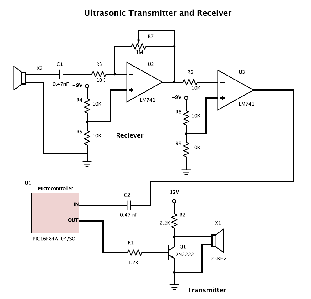
The goal is to create two circuits: one transmitter and one receiver for ultrasound applications. A pair of 25 kHz transmitter and receiver units is already available. To design an ultrasound transmitter and receiver circuit operating at 25 kHz, the...
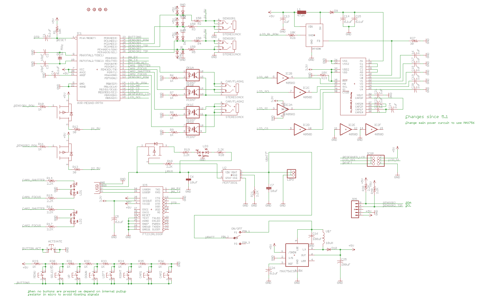
Previously, a linear regulator was used, but a Max756 boost converter is now in operation. An output ripple of 0.1 to 0.3V is observed in the current, while the Max756 datasheet indicates an expected ripple of about 50 mA....
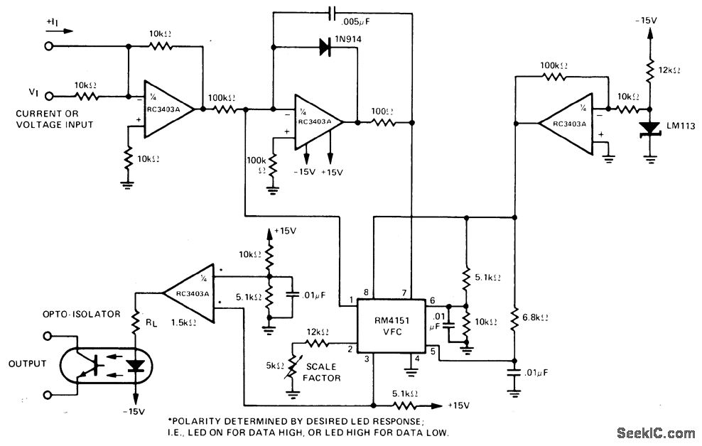
The input voltage range of 0-10 V is converted to a proportional frequency at the output of an optoisolator using the RM4151 converter. This converter is paired with the RC3403A quad op-amp, which serves multiple functions including inverter, integrator,...
This circuit employs a phototransistor along with four operational amplifiers to function as a total energy detector. It is designed to measure the total energy of optical pulses transmitted through an optical cable communication system. When the light intensity...
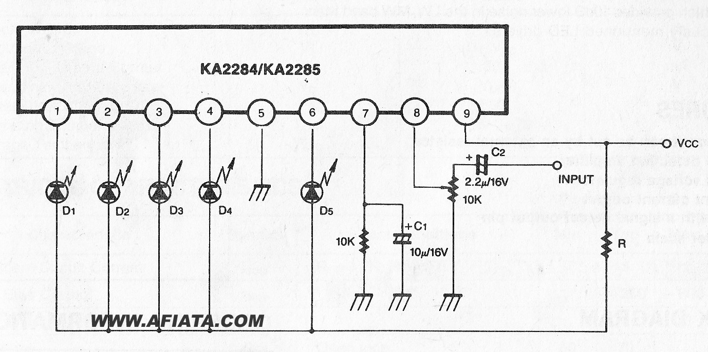
The KA2284 is a monolithic integrated circuit designed for 5-dot LED level meter drives with a built-in rectifying amplifier. It is suitable for both AC and DC level meters, such as VU meters or signal meters. The KA2284 integrated circuit...
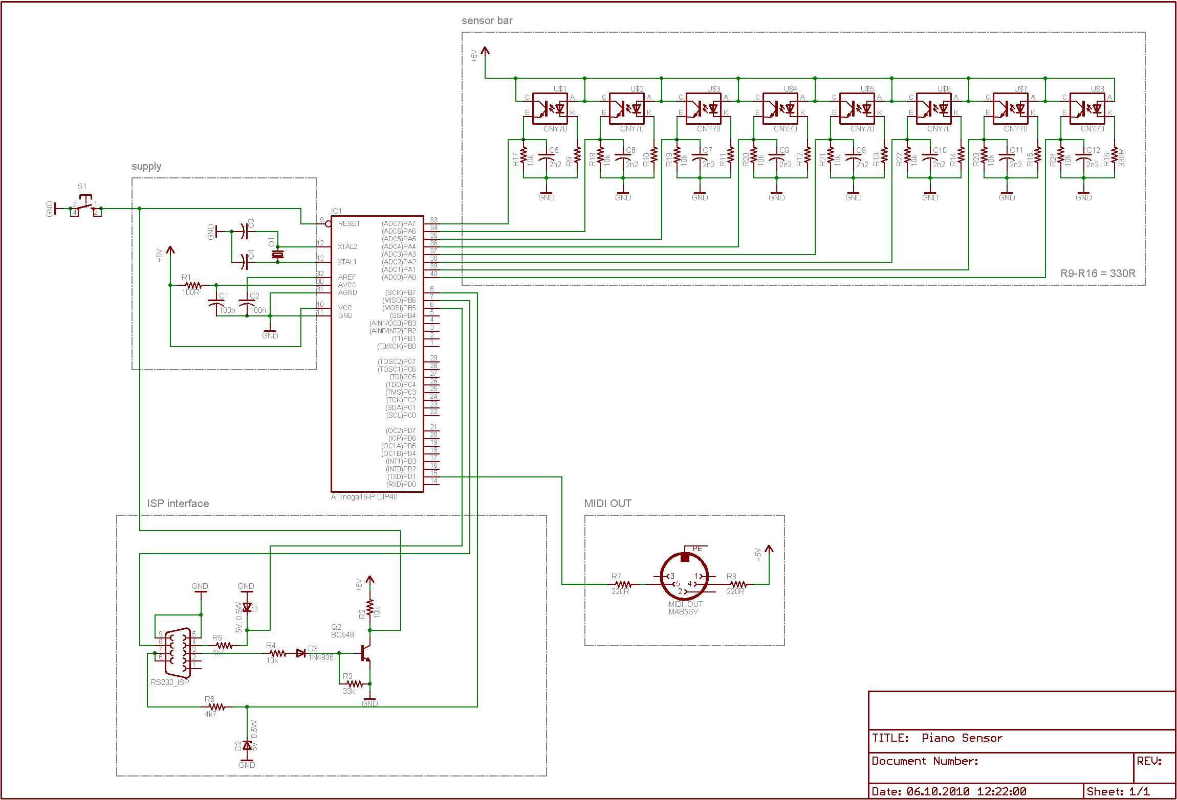
An effort is being made to enhance the responsiveness of an electronic keyboard due to dissatisfaction with the current sensitivity to keystrokes. The initial step in this process involves measuring the speed of the fastest keystroke. To improve the responsiveness...