
DIGITAL ENTRY LOCK

The circuit design features a keypad interface for user input, allowing for secure access control through a four-digit code. The keypad connects to a 24-pin header, where jumpers can be configured to set the desired access code. The LST220 (U1) serves as the core logic component, interpreting the signals from the keypad. It is designed to recognize a specific sequence of four digits, ensuring that only authorized users can gain access.
When the correct code is entered, a high signal is generated at pin 13 of U1. This signal is utilized to drive a transistor (Q1), which acts as a switch to control the current flow to the relay (K1). The relay is responsible for activating an external electric lock solenoid, thereby unlocking the door or access point.
The circuit should also include necessary debouncing mechanisms for the keypad to prevent false triggering due to mechanical noise when keys are pressed. Additional components such as resistors and capacitors may be used to stabilize the power supply to U1 and ensure reliable operation. Optional features could include LED indicators to provide visual feedback when the correct code is entered or audible alerts for incorrect entries.
Overall, this electronic schematic provides a straightforward and effective method for implementing a secure access control system using a keypad and relay mechanism.A keypad enters a four-digit access code, which is programmed via jumpers on a 24-pin plug-in header and socket. U1 is an LST220, which detects a four-digit sequential data input. When the correct data is entered into the keyboard, pin 13 of U1 goes high, which activates Q1 and K1.
K1 drives an external electric lock solenoid, etc. 🔗 External reference
Related Circuits

This digital dice circuit is designed to display numbers effectively. When the spin switch is turned off, it converts the input into a binary format using a diode matrix composed of diodes D1 to D9 (1N4148 or 1N914). This...
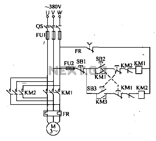
The forward and reverse dual interlock control circuit is based on the control circuit depicted in Figure 4-4, with an enhancement that incorporates a composite mechanical button interlock. The advantage of this circuit is that it allows the motor...
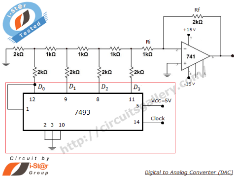
A Digital to Analog Converter (DAC) is utilized to produce an analog voltage that corresponds to input digital data. Binary data can be transformed into its analog equivalent using an R-2R ladder network combined with a summing amplifier, which...
The frequency counter is designed to measure the number of cycles per second of an incoming signal. A counting device is necessary for this purpose, and in electronic circuits, counter integrated circuits (ICs) are available for counting input pulses....
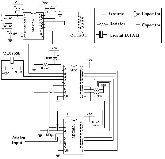
Data Collection - Analog to Digital Conversion and Communicating with a PC through the Serial Port Microcontroller Advanced Kit. The system described involves the process of data collection through analog-to-digital conversion, enabling communication with a personal computer via a serial...
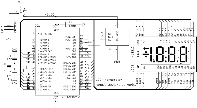
The circuit drives the LCD pins with 50% square waves. Each segment on this LCD is connected to the COM backplane and a separate pin. When a pin is driven in phase with the COM pin, the corresponding LCD...