
Infrared Remote Tester circuit

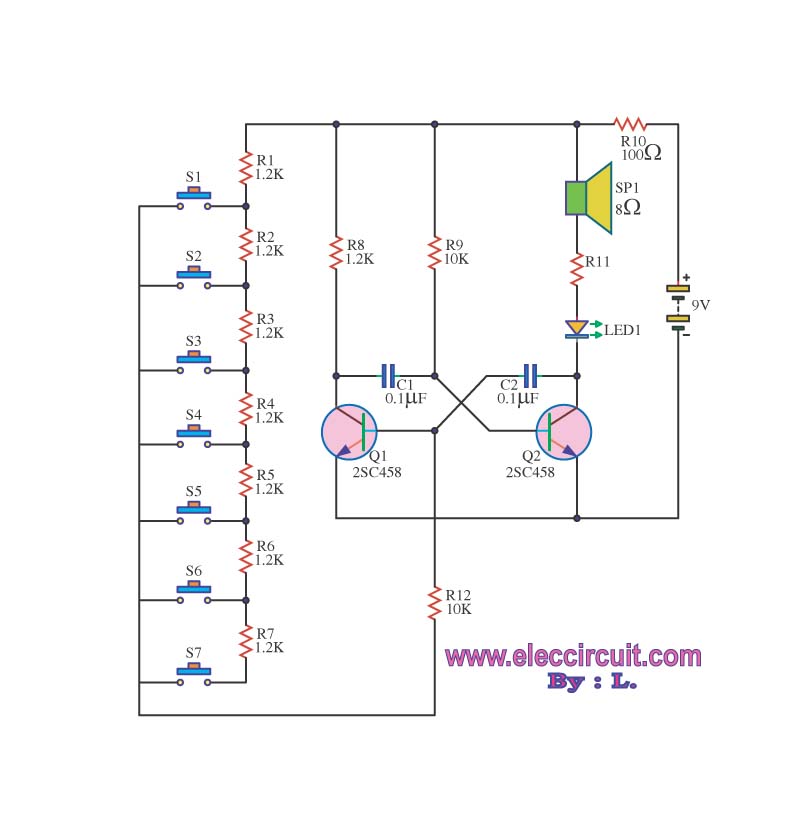
The infrared remote control tester circuit consists of a few key components, including a phototransistor (Q1), a light-emitting diode (LED), and a resistor to limit the current through the LED. The phototransistor is sensitive to infrared light emitted by the remote control's infrared LED when a button is pressed.
When the infrared light from the remote control reaches the phototransistor, it generates a small current that activates the LED, causing it to flash. This visual indication confirms that the remote control is functioning and emitting signals. The circuit is designed to operate effectively within a range of 20 to 25 cm, which is suitable for typical testing scenarios.
The configuration of the circuit is straightforward. The phototransistor is connected in such a way that it can detect infrared signals and control the LED's state. A resistor is placed in series with the LED to prevent excessive current flow, ensuring the longevity of the LED.
To build the circuit, the following steps can be followed:
1. Connect the collector of the phototransistor to the positive terminal of the power supply.
2. Connect the emitter of the phototransistor to one terminal of the LED.
3. Connect the other terminal of the LED to ground through a current-limiting resistor.
4. Ensure that the phototransistor is oriented properly to receive the infrared signals from the remote control.
This simple yet effective circuit serves as a valuable tool for electronics enthusiasts, providing a quick and reliable method for testing remote controls.A very simple device allowing a quick check of common Infra-red Remote-Controls can be useful to the electronics amateur, frequently asked to repair or test these ubiquitous devices. A reliable circuit was designed with a handful of components: the LED will flash when any of the Remote-Control push buttons will be pressed.
The side of the Remote-Control bearing the IR emitting diode(s) must be directed towards the Photo Transistor (Q1) of the checker circuit: maximum distance should not exceed about 20 - 25cm.. 🔗 External reference
Related Circuits
This project involves a straightforward and practical 12V power supply circuit utilizing the LM7812 integrated circuit (IC). The LM7812 is a three-terminal fixed voltage regulator IC housed in a TO-220 package. It incorporates several built-in features such as thermal...
The circuit operates as an astable multivibrator, generating a square wave signal at a specific frequency. When powered, the circuit will function continuously. The astable multivibrator circuit is a type of oscillator that produces a continuous square wave output without...
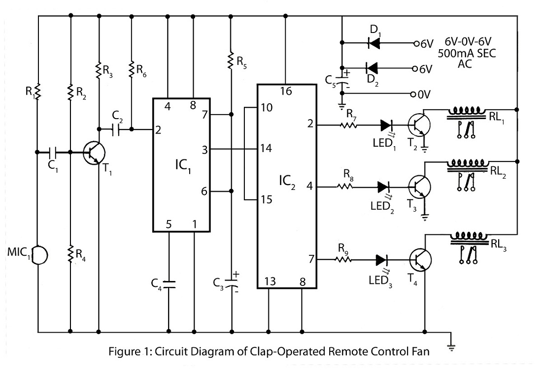
The clap-operated remote control for fans is designed to control a ten-step speed fan circuit. This includes a circuit diagram and a description of the clap-operated remote control system for fans. The clap-operated remote control system utilizes sound recognition to...
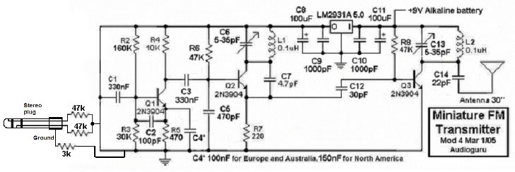
This small FM transmitter can be modified to replace the microphone with an audio jack, allowing it to connect to an MP3 player for audio playback through car audio systems. The design is straightforward and intended for a short...
The two circuits di atas illustrate opening a relay contact a short time after the ignition or light switch is turned off. The capacitor is charged and the relay is closed when the voltage at the diode anode rises...
This circuit is designed to check the condition of lead-acid and gel cell batteries with capacities greater than 20Ah. It switches a load of about 18A at a rate close to 50Hz so that the internal resistance of the...