
Keyboard - Display Interface Circuit

The 4x4 matrix keyboard system is structured to facilitate user interaction with the microcontroller, allowing for versatile control of various parameters. Each of the numeric keys (0-9) and function keys (A-F) is arranged in a matrix format, which enables efficient scanning and detection of key presses. The implementation of the 8255A programmable interface chip is crucial, as it manages both input from the keyboard and output to the display, ensuring seamless communication between the user interface and the microcontroller.
In terms of functionality, the keyboard is capable of initiating different operational modes, including automatic or manual arrangements, which could be critical for applications requiring user-defined settings. The static display, driven by the 74LS48 decoder/driver, presents the selected parameters clearly to the user, while the 74LS373 latch maintains the state of the display during operation.
The keyboard matrix is scanned by the microcontroller through the designated ports of the 8255A. When a key is pressed, the corresponding row and column are activated, allowing the microcontroller to identify which key has been pressed. This information is crucial for executing the appropriate command, whether it be adjusting parameters or selecting different operational modes. The dual functionality of the 8255A port B, switching between output and input modes, enhances the efficiency of the system, allowing it to respond promptly to user inputs while simultaneously providing visual feedback through the display.
Overall, the design of the 4x4 matrix keyboard system, in conjunction with the 8255A programmable interface chip and associated components, creates a robust and user-friendly interface for managing various system settings and operations.4X4 matrix keyboard system settings, including 0 ~ 9 numeric keys. A ~ F as function keys. The main function of the keyboard is complete parameter settings, display mode select ion, start automatic/manual arrangements, as well as the system and stop. Keyboard and display interface chip 8255A programmable circuit and connected to the microcontroller circuit shown in Figure 27-48. from this picture, you can see. 8255A to the B port as the display interface. The system uses a static display, 74LS373 as a latch. 74LS48 for the common cathode decoder/driver, LED digital tube with CS5137T. 44 keyboard matrix keyboard. 8255A port PA3-PAO row scan connection port column values from port B PB3 ~ PBO read people, to deal with the system keyboard interrupt.
Thus, 8255A port B to work in two ways under: In the display state is output; the keyboard interrupt service routine processing input mode. To do this, just in front of the corresponding operation re 8255A new settings work.
Related Circuits
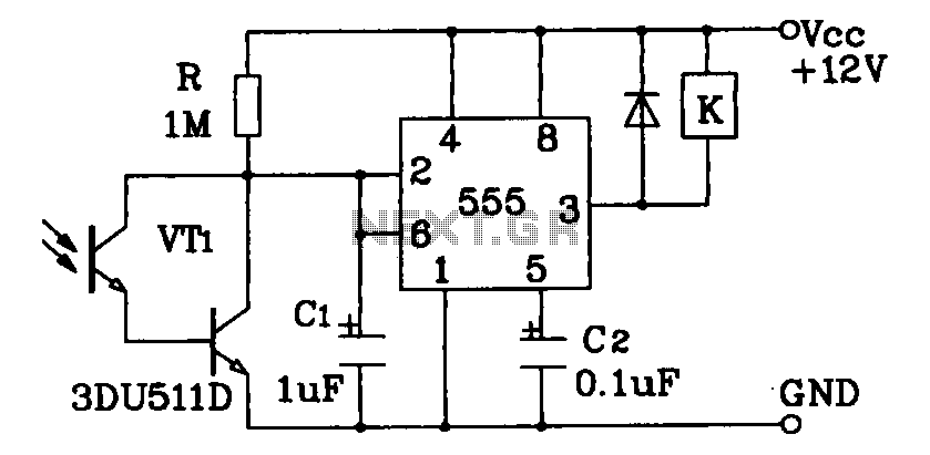
Darlington phototransistor type light-sensitive switch control circuit application. The Darlington type phototransistor serves as a sensitive element, capable of detecting low light levels for the detection of reflected light signals. The Darlington phototransistor circuit utilizes a pair of transistors configured...
The Clock Controller was designed as an exemplary application of the C programming language to manage timer0 interrupts, control a 7-segment LED display, and perform keypad scanning. It offers a 1-bit sink current output suitable for driving devices such...
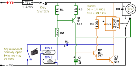
The schematic illustrates a Simple Motorcycle Alarm Circuit Diagram created by Ron J. It incorporates micro-switches to safeguard removable panels and... The Simple Motorcycle Alarm Circuit Diagram is designed to enhance the security of motorcycles by utilizing a series of...
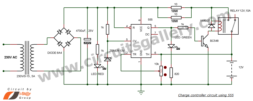
This is a simple DIY charge controller schematic created in response to a request from one of the readers on our Facebook page. The primary component of this automatic battery charger circuit is a 555 timer, which compares the...

This inverter circuit is designed to power electric razors, stroboscopes, flash tubes, and small fluorescent lamps using a 12-volt car battery. Unlike typical feedback oscillator inverters, this design features a separate oscillator from the output stage, allowing for easy...
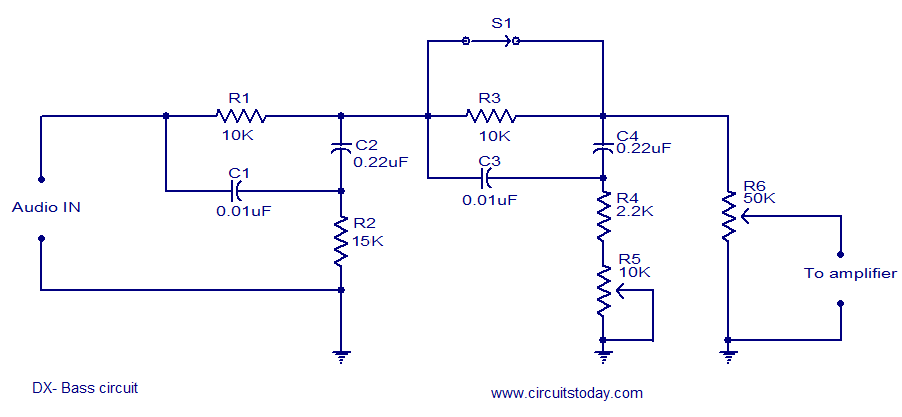
The circuit diagram of a passive DX bass circuit is presented, which is compatible with nearly all audio amplifiers. This design was created by Mr. Emmanuel Chipula from Malawi and submitted for publication. Laboratory tests confirmed satisfactory performance. Credit...