
MOSFET current sensing

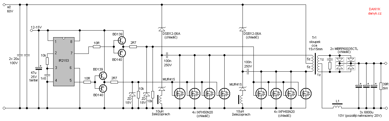
The described circuit utilizes a current sensing technique through a MOSFET, leveraging its resistive characteristics when fully turned on. In this configuration, the MOSFET operates in the saturation region, where it behaves similarly to a resistor. The method involves monitoring the voltage across the MOSFET to infer the current flowing through it. This is achieved by placing a sense resistor in series with the MOSFET, allowing the voltage drop across this resistor to be proportional to the current.
The primary advantage of using a MOSFET for current sensing is its positive temperature coefficient of on-resistance (R_on). As the temperature increases, R_on also increases, which in turn causes a reduction in current for a given voltage. This thermal feedback mechanism is beneficial in protecting the MOSFET from overheating, as it inherently limits the current when the device heats up.
To implement this circuit effectively, it is crucial to select a MOSFET with appropriate specifications, including maximum current rating, R_on, and thermal characteristics. Additionally, a suitable sense resistor must be chosen to ensure that the voltage drop is within measurable limits while maintaining minimal impact on the overall circuit performance.
For accurate current sensing, operational amplifiers can be utilized to amplify the voltage across the sense resistor, providing a more manageable signal for further processing or for use in feedback control loops. This configuration is particularly useful in applications such as power management systems, battery monitoring, and motor control, where precise current measurements are essential for system stability and efficiency.
Overall, this circuit design exemplifies the effective use of a MOSFET in current sensing applications, highlighting the importance of thermal characteristics and the relationship between voltage and current in maintaining device safety and performance.The circuit shows the method of `mirror` current sensing a MOSFET. A fully conducting MOSFET is resistive and behaves exactly as a resistor. It therefore you limit the voltage across the MOSFET when it is conducting you automatically limit the current flowing through it. In addition the MOSFET``s on resistance has a positive temperature coefficient so as it warms up, keeping the voltage across it limited will automatically reduce the limited current flowing through it, keeping it within its safe region over a wide range of junction temperatures.
🔗 External reference
Related Circuits
Occasionally, a low voltage power supply capable of delivering very high currents (hundreds of amperes) is required for applications such as spot welding, heating or melting metals, starting vehicle engines, or conducting various physical experiments. A decision has been...
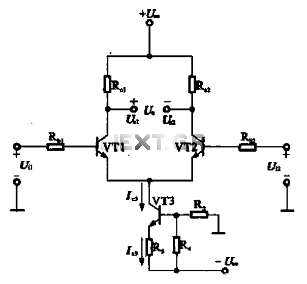
A constant current source is utilized in the differential amplifier circuit, which includes an emitter resistor. In this configuration, an increase in the output voltage (Ua) is not desirable. To ensure that Ua remains stable, the supply voltage (Ucc)...
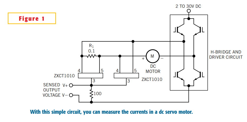
The simple circuit design in Figure 1 lets you measure all components of a current flowing in a dc servo motor. The rectified output of the circuit uses ground as a reference, so you can measure the output by...
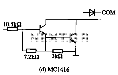
The MC1411 series features a Darlington drive current internal structure that offers small, consistent, and highly reliable parameters. This series is particularly effective for high-voltage applications and can directly drive loads such as relays and lights. It includes wheeling...

A step-up converter can be designed using the MAX641 integrated circuit from Maxim IC, utilizing a minimal number of electronic components. This high-voltage step-up converter project can deliver a maximum output current of up to 1A. The low battery...
The following circuit illustrates a High Voltage, Low Current Supply. Features: This circuit is utilized for applications such as biasing gas-discharge tubes, radiation detectors, and similar devices. The High Voltage, Low Current Supply circuit is designed to provide a stable...