
Dipole antenna for two metres

The described antenna is a simple yet effective omnidirectional, vertically-polarized dipole designed for operation on the two-meter amateur radio band. Constructed from 50-ohm RG58 coaxial cable, this antenna can be rolled for convenient storage and is suitable for both indoor and outdoor applications, provided it is waterproofed for external use.
The design utilizes a single length of coaxial cable, which serves as both the antenna element and the feedline. The construction process involves removing a quarter wavelength of the outer jacket from the coax, which is approximately 48 centimeters for the two-meter band. The exposed braid is then bent back towards the transceiver, forming a vertical dipole configuration. This design minimizes the need for additional metal components or complex wiring, simplifying the assembly process.
Key components required for assembly include 3-4 meters of RG58 coaxial cable, a PL259 or BNC plug compatible with the transceiver, a small metal lug or nut for securing the inner conductor, and basic hand tools such as scissors, a tape measure, a small screwdriver, long-nosed pliers, and a soldering iron. The construction begins with soldering the chosen connector to one end of the coax cable. The opposite end requires careful stripping of the outer jacket to expose the braid and inner conductor. A small hole is created in the braid to facilitate the emergence of the inner conductor, which is then secured to a metal lug.
For optimal performance, the antenna should be erected vertically and positioned away from metallic objects to prevent interference. Height is crucial, as raising the antenna enhances signal reception. In environments with weak signals, situating the antenna near a window facing the signal source can improve performance. If used outdoors, it is essential to apply a sealing compound to the cable to prevent moisture ingress, which can lead to increased cable losses over time and diminish performance.
Regular checks of the standing wave ratio (SWR) are recommended to ensure efficient operation. Adjustments to the antenna length may be necessary if the SWR exceeds 1.5:1 at the operating frequency of 147 MHz. With a total construction time of approximately 20 minutes and a low cost of around five to ten dollars, this omnidirectional dipole presents an accessible solution for amateur radio enthusiasts seeking to enhance their communication capabilities.Described here is a simple omnidirectional, vertically-polarised dipole for two metres. Made from coaxial cable, it can be rolled up and stored in a small container. It may be used as is indoors, or waterproofed for use outside. No extravagant gain claims are made; this dipole has no more gain than any other. However, it should be significantly more effective than the antenna that came with your handheld. The cost of building the project is around five to ten dollars. Allow about 20 minutes to construct and erect the antenna. A single length of 50 ohm coaxial cable forms both the antenna element and the feedline. The antenna is made by removing a quarter wavelength of outer jacket and bending the braid back along the cable towards the transceiver to form a vertical dipole. This means no metal work or wiring is required (apart from attaching the BNC or PL259 plug). Parts required: 3-4m RG58 coaxial cable (not critical - use longer length if height is needed or the operating position is distant from the antenna) PL259 or BNC plug (to suit transceiver) small metal lug, washer or nut tape measure, scissors, small screwdriver, long-nosed pliers, multimeter, fishing line, soldering iron.
Construction: Solder the PL259 or BNC plug to one end of the RG58 cable. From the other end of the cable remove 48 cm of the black plastic outer covering to expose the braid. With a small screwdriver (Phillips head is best) gently part the braid to make a small hole near where it ceases to be covered by the plastic jacket.
Aim to make it about 5mm in diameter. Use either pliers or a screwdriver to pull the inner conductor out from inside the braid through the hole in the braid (Fig 2c). Fold the braid back along the cable towards the plug. Solder the end of the braid to prevent fraying. Remove about 5mm insulation from the inner conductor. Solder the end of the inner conductor to a small metal lug or nut. Thread fishing line through the lug or nut and hang the antenna in its desired position. The antenna is now operational. You may wish to check the SWR and make it longer or shorter if the SWR is above about 1.5:1 at 147 MHz.
Erection and use. The antenna should be hung vertically for best performance. Keep it away from metal objects and have it as high as possible. Where signals are weak, hang the antenna near a window facing the repeater. If you intend to use the antenna outside, apply sealing compound to stop moisture entering the cable. Not doing this will mean poorer performance over time as cable losses increase. 🔗 External reference
Related Circuits

A simple linear voltage-controlled amplifier can be constructed with one operational amplifier (op amp) and two junction field-effect transistors (JFETs). This amplifier can achieve an 80-dB dynamic control range with less than ±0.2% linearity error for 0 V. The described...
Utilize this FM antenna amplifier in locations where the reception of FM stations is poor. This circuit is specifically designed for this purpose. The FM antenna amplifier circuit is engineered to enhance signal strength for FM radio stations, particularly in...
The construction is nearly complete, and a circuit diagram has been created. The design has been finalized and documented on paper. The circuit diagram represents a critical stage in the development of an electronic project, serving as a blueprint for...
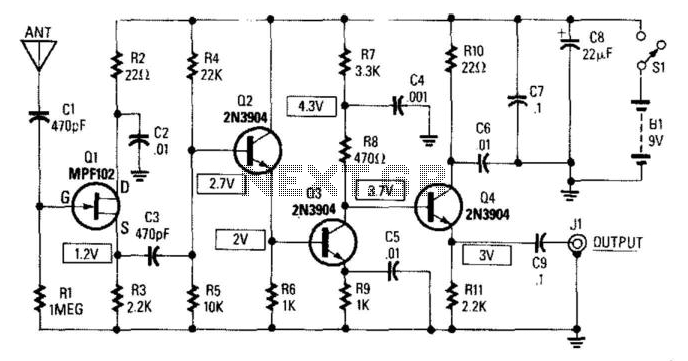
This circuit provides a gain of 14 to 20 dB at frequencies ranging from 10 kHz to 30 MHz. The antenna length can vary between 5 and 10 feet, with a 102-inch CB whip being particularly suitable for this...
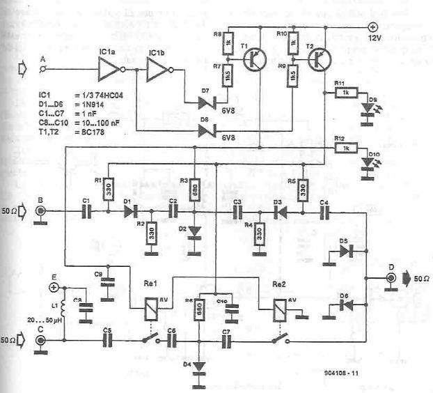
This antenna selector circuit diagram electronic project is constructed using standard electronic components and facilitates the switching between two FM antennas through a logic signal. The gates IC1b and IC1a manage the switching and interface between the required logic...
Homemade antennas can significantly enhance the performance of AM and FM radios, short-wave receivers, and scanners. For enthusiasts of talk radio, experimenting with AM band antennas can lead to the ability to receive broadcasts from across the country with...