
Display Driver circuit

The CD4033 is a versatile decade counter that can be utilized to drive a Seven Segment Display effectively. It operates in a way that each output corresponds to a specific count, allowing for the display of decimal digits from 0 to 9. The primary advantage of using the CD4033 in this application is its ability to provide a simple and efficient means of controlling the display with minimal external components.
In this circuit, the CD4033 is connected to the Seven Segment Display through a series of output pins. Each of these pins is responsible for illuminating specific segments of the display, which are typically labeled a through g. When the counter increments, the corresponding segments light up in a pattern that represents the current count.
The circuit can be powered by a standard DC voltage supply, typically in the range of 5V to 15V, depending on the specifications of the CD4033 and the display. Additionally, resistors may be included in series with the segments to limit current and prevent damage to the LEDs in the display.
The operation of the circuit can be further enhanced by incorporating a clock signal to synchronize the counting process. This can be achieved using a simple oscillator circuit or a microcontroller that generates a square wave signal. By adjusting the frequency of the clock signal, the speed at which the display counts can be modified, allowing for greater flexibility in applications.
Overall, this display driver circuit is an effective solution for visual representation of numerical data, leveraging the capabilities of the CD4033 to simplify the design and implementation of a Seven Segment Display driver.This display driver circuit shows how a Seven Segment Display is driving with the help of the 5 stage Johnson decade counter IC CD4033.The IC has counter a.. 🔗 External reference
Related Circuits
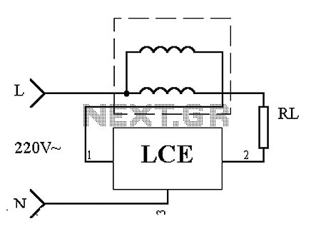
This is an application circuit of the device as illustrated in principle. In the meter, the voltage and current coils are connected to the power line, regardless of whether a load is connected. The voltage coil consistently draws power,...
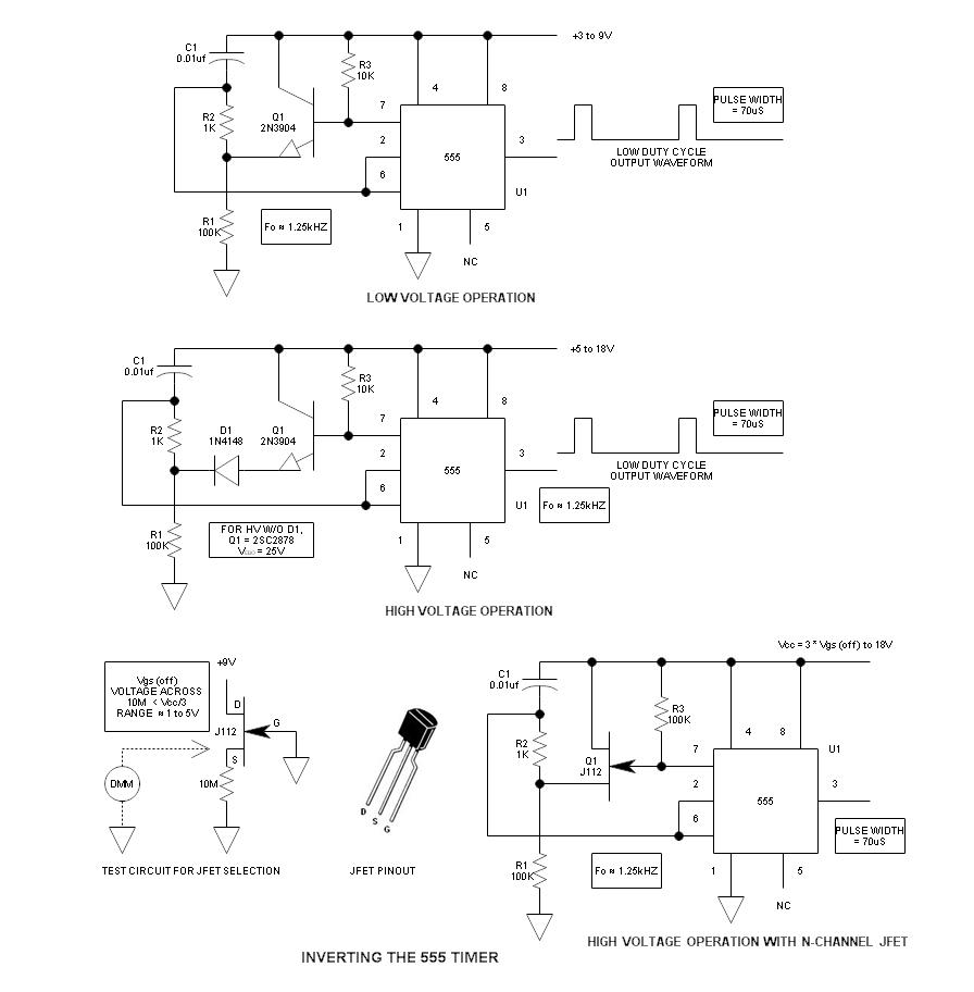
When using the 555 timer, the output polarity often appears to be incorrect, as the 555 typically cannot produce a duty cycle of less than 50%. This inverted 555 circuit is capable of generating duty cycles below 50%. The...
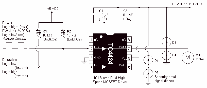
Physical motion of some form helps differentiate a robot from a computer. It would be nice if a motor could be attached directly to a chip that controlled the movement. But, most chips can't pass enough current or voltage...
A 12V battery pack from a PowerWheels car is used alongside two wooden planks with several nails driven through them. Each nail is wrapped with speaker wire that connects to ignitors, while the other end returns to a central...
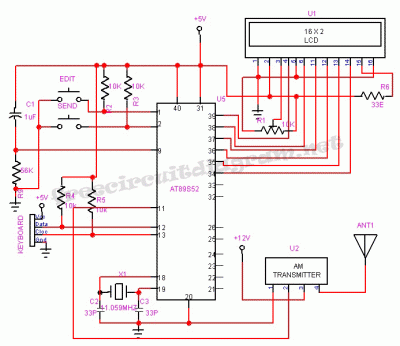
This system is designed to communicate or transmit a text message from one location to another using a wireless circuit. The text message is encrypted with a microcontroller, and the encrypted message is transmitted wirelessly. At the receiving end,...
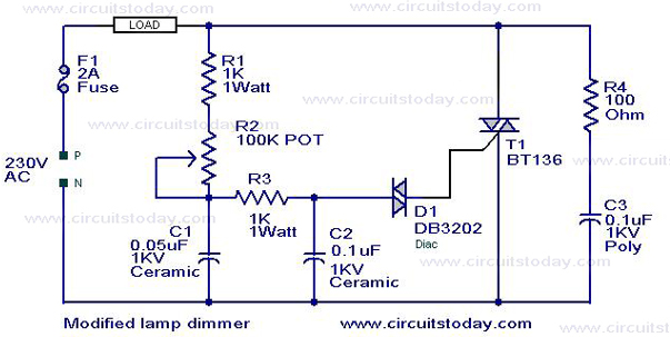
This is a modification of the Simple Lamp Dimmer/Fan Regulator circuit that was previously posted. The operation of the circuit remains the same as the original; however, it now includes a snubber circuit composed of resistor R4 and capacitor...