
water sensor circuit using 555 timer
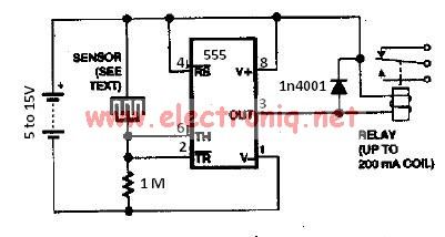
The water sensor circuit operates by detecting the presence of water through conductivity. The two electrodes serve as a sensing element; when water bridges the gap between them, it completes the circuit, allowing current to flow. The 555 timer is used in a monostable mode, which means that it produces a single output pulse when triggered. In this application, the output pulse indicates the presence of water.
The circuit can be designed with a few key components: the 555 timer IC, two metal electrodes, a resistor, and a power supply. The configuration of the 555 timer is crucial, as it determines the timing characteristics of the output pulse. The resistor value directly influences the sensitivity of the circuit. A higher resistance value, such as 2.2 MΩ, increases the sensitivity, allowing the circuit to detect even minimal amounts of water. Conversely, if the circuit is overly sensitive and generates false alarms, reducing the resistor to 220 kΩ can help mitigate this issue.
In terms of layout, the electrodes should be placed in a location where water accumulation is expected. The circuit board should be designed to prevent corrosion of the electrodes, which can affect long-term reliability. Additionally, proper filtering capacitors may be added to the power supply lines to reduce noise that could interfere with the sensor's operation.
Overall, the water sensor circuit based on a 555 timer is a straightforward yet effective solution for water detection applications, providing a reliable means to monitor moisture levels in various environments.The water sensor circuit is based on a 555 timer circuit and come common electronic components. The water sensor is made by two metal electrodes arranged very close that a drop of water (liquid) will bridge them. If the liquid ( water ) is very pure you may change the resistor value to 2. 2m ohms and if the circuit is give false alarm sensing you may change the value of resistor to 220k. 🔗 External reference
Related Circuits
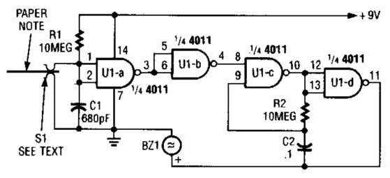
This device prevents paper notes and memos from being overlooked. A paper note placed between two fingers made of a conducting material (metal or conductive plastic) breaks the circuit, allowing pair 1 of Ul-a to go high. The goal...
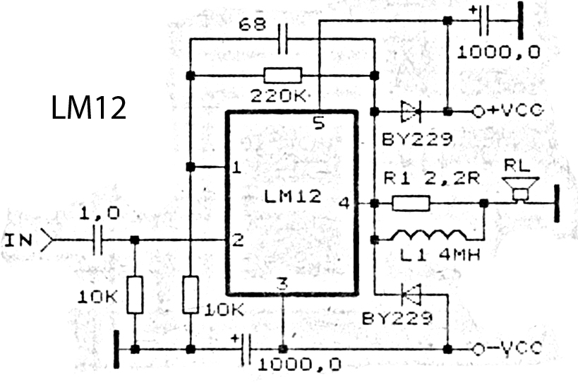
This is an amplifier circuit utilizing the LM12 integrated circuit as the primary amplifier. The amplifier delivers a power output of 150 watts and operates with a load impedance of 4 ohms. It is classified as a high-output power...

This circuit emits an intermittent beep or flashes an LED when the water level in a container reaches a predetermined point. It is designed to be mounted on top of the container, such as a plastic tank, using two...
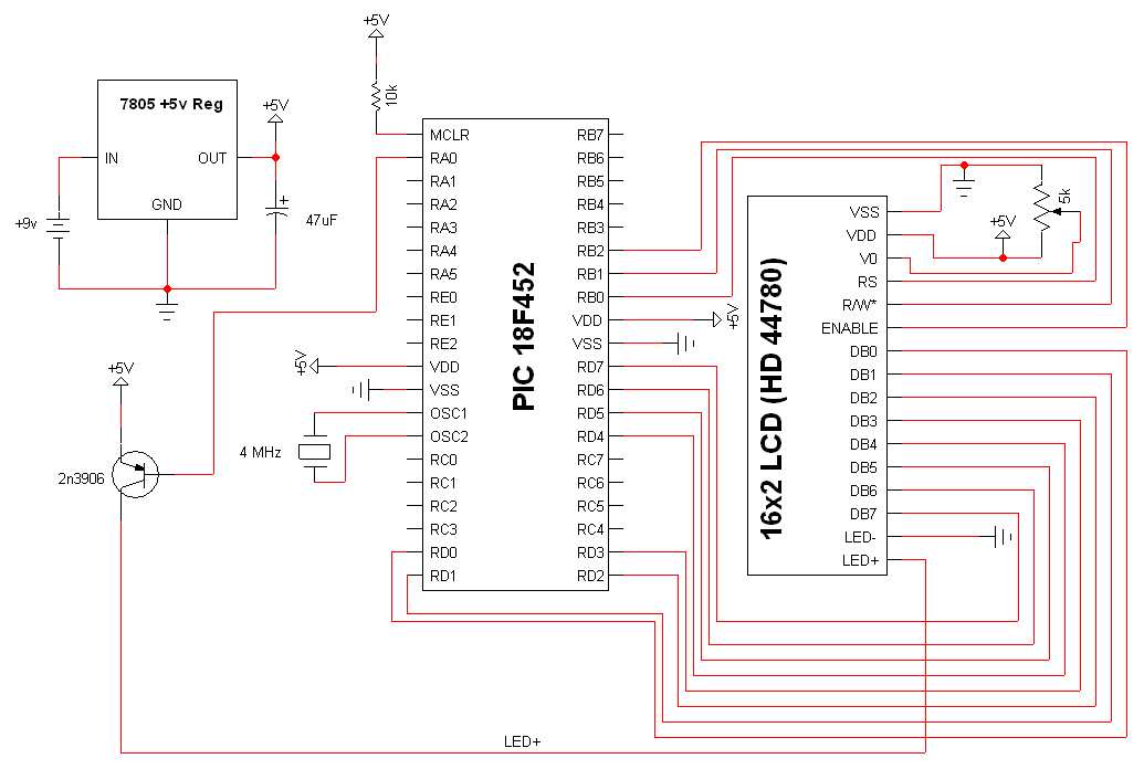
The electronic designs for the two animatronic mouths are presented below. The first design is for the articulated mouth, with additional servos for the eyebrows and eyes. The second design is for the LCD mouth, which closely resembles the...
The electromagnetic RBI timer features a simple structure, is cost-effective, and is commonly utilized in high school physics experiments. However, a significant drawback of the electromagnetic RBI timer is the substantial errors it produces during experiments. This issue arises...
One of the simplest methods of metal detecting is through a beat frequency oscillator. The circuit consists of two balanced oscillators: one provides a reference signal, while the other acts as the detector element. The frequency of the reference...