
DIY Test Equipment for Audio and Ham Radio Enthusiasts

The described device is engineered to enhance the performance and reliability of the input stage in a circuit utilizing a TO-220 package, which is commonly used for power transistors and other high-power components. The new PCB is designed to accommodate improved driver circuitry that may include components such as operational amplifiers, resistors, and capacitors, which are essential for optimal signal conditioning and amplification.
The replacement process involves careful removal of the original driver board, ensuring that the connections to the TO-220 package are preserved. The new PCB should be designed with a layout that minimizes parasitic inductance and capacitance, enhancing the overall performance of the device. Key considerations in the design include thermal management, as the TO-220 package is often used in high-power applications that generate significant heat. Adequate heat sinking and thermal vias may be incorporated into the PCB design to ensure efficient heat dissipation.
Furthermore, the new driver board may feature improved trace routing for power and signal lines, reducing the likelihood of electromagnetic interference (EMI) and enhancing the integrity of the signals being processed. The use of high-quality components on the new PCB can lead to improved reliability and longevity of the device, making it suitable for various applications in power electronics, audio amplification, and other fields requiring robust performance.
In summary, this compact device represents a significant upgrade over the original design, providing enhanced functionality and reliability through the implementation of a custom-designed printed circuit board tailored to the specific needs of the application.This neat device replaces the input transistors and associated circuitry on one TO-220 style device. I had some driver boards made by my printed circuit house and decided that replacing the original driver board with the new PCB. 🔗 External reference
Related Circuits

This article aims to illustrate a basic optical LED wireless link for transmitting high-definition (HD) S/PDIF digital audio streams. Circuit designs for both the transmitter (optical modulator) and receiver are provided, utilizing cost-effective op-amp configurations. Specific components are listed,...
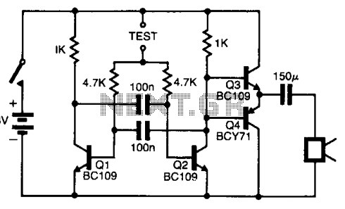
The pitch of the tone is dependent upon the resistance under test. The tester will respond to resistance of hundreds of kilohms, yet it is possible to distinguish differences of just a few tens of ohms in low-resistance circuits....
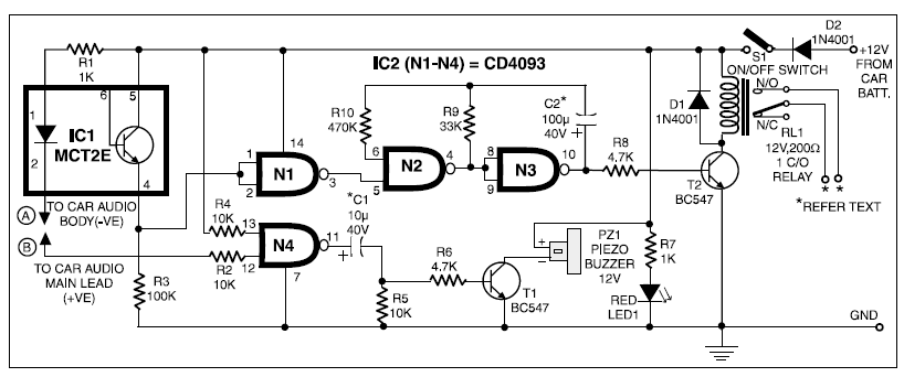
When 12V DC from the car battery is applied to the device (as indicated by LED1) through switch S1, the circuit enters standby mode. The LED inside the optocoupler IC1 illuminates as its cathode terminal is grounded via the...
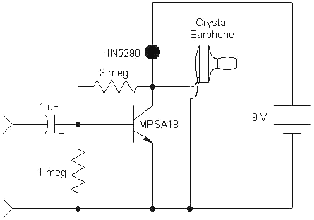
This simple, one-transistor amplifier provides a voltage gain of over 1000 (60 dB) for an active aerial impedance crystal earphone. The gain is achieved by replacing the standard load resistor with a constant-current diode that supplies 1/2 mA while...
The direct coupling audio power amplifier utilizes an integrated operational amplifier. There are typically two practical configurations. The first configuration, depicted in (a), features a circuit structure that includes the output of the operational amplifier and a complementary symmetry...
The RF signal is transmitted from the antenna through CI to a tuned circuit consisting of LI and C2. One end of L2 delivers the RF signal to the base of Q1 for amplification, while the other end connects...