
Donald Smith Devices too good to be true 30

A schematic is a representation of an electrical circuit that illustrates the components and their connections using standardized symbols. In this case, the schematic likely includes various elements such as resistors, capacitors, inductors, diodes, and transistors, which are essential for the functioning of the circuit. Each component will be labeled with its respective value or part number, and connections will be clearly indicated, often using lines that represent wires.
When creating a schematic, it is crucial to ensure that all components are accurately represented and that the connections reflect the intended circuit design. This involves understanding the function of each component within the circuit, including how they interact with each other. For instance, resistors may be used to limit current, while capacitors might be included for filtering or energy storage purposes.
In addition to the basic components, the schematic may also feature power supply connections, ground references, and signal pathways. It is essential to maintain clarity in the schematic to facilitate troubleshooting and modifications in the future. Proper organization and labeling are key to creating an effective schematic that can be easily interpreted by other engineers or technicians.
Overall, the process of creating a schematic based on video tutorials requires careful attention to detail and a solid understanding of electronic principles to ensure that the final representation accurately reflects the intended design.Hi Dragon thank`s very much for your great info. I have rewatched all your video (or at least Lenz or Znel video) And i made a shematic how i see the.. 🔗 External reference
Related Circuits

This is a design for a sawtooth generator circuit. The advantage of this circuit is its low cost and the capability to produce an auxiliary square wave at the same frequency. This circuit can be utilized to sweep the...
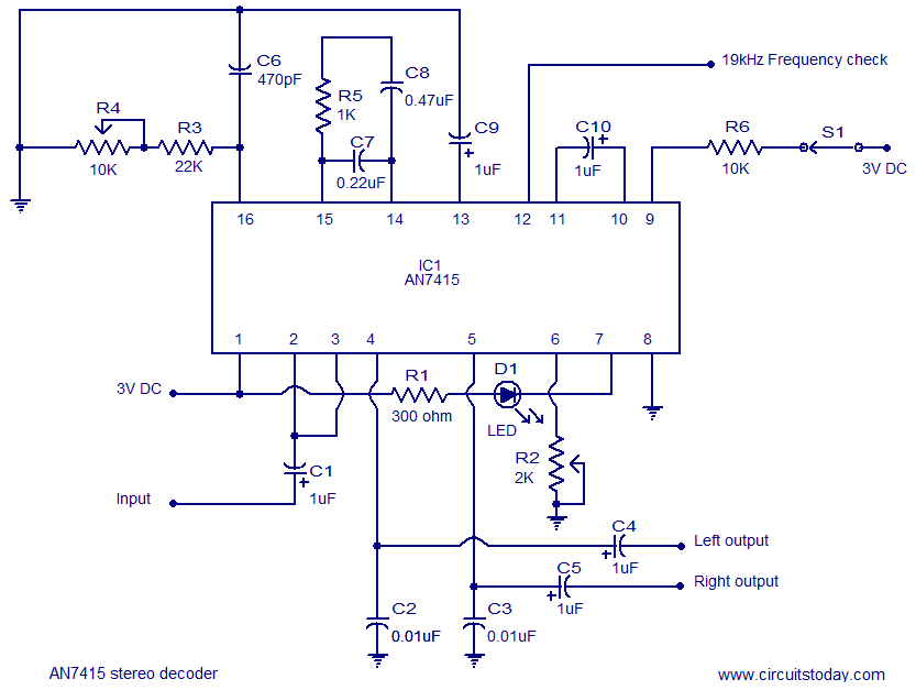
AN7415 based FM stereo demodulator circuit. 1.6 to 7V operating voltage range. High gain and low distortion. The AN7415 is a versatile integrated circuit designed for FM stereo demodulation applications. This circuit operates within a voltage range of 1.6 to...
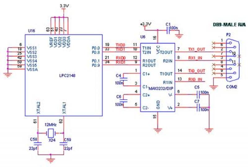
The interfacing of a Bluetooth module with the LPC2148 microcontroller is a straightforward process that enables the transmission of messages from the LPC2148 Primer Board to mobile devices via Bluetooth using UART0. Some delays may occur when sending a...
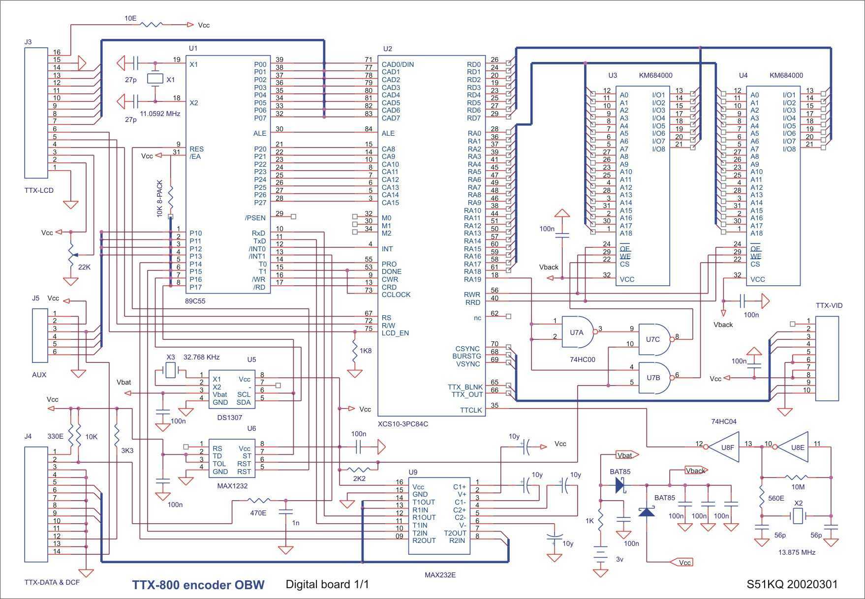
Test signals inserted in the lines of the vertical blanking interval, defined by the TV standard, e.g. for the 625 standard the CCIR together with the EBU issued the formal specifications for the signals inserted in lines 17, 18,...
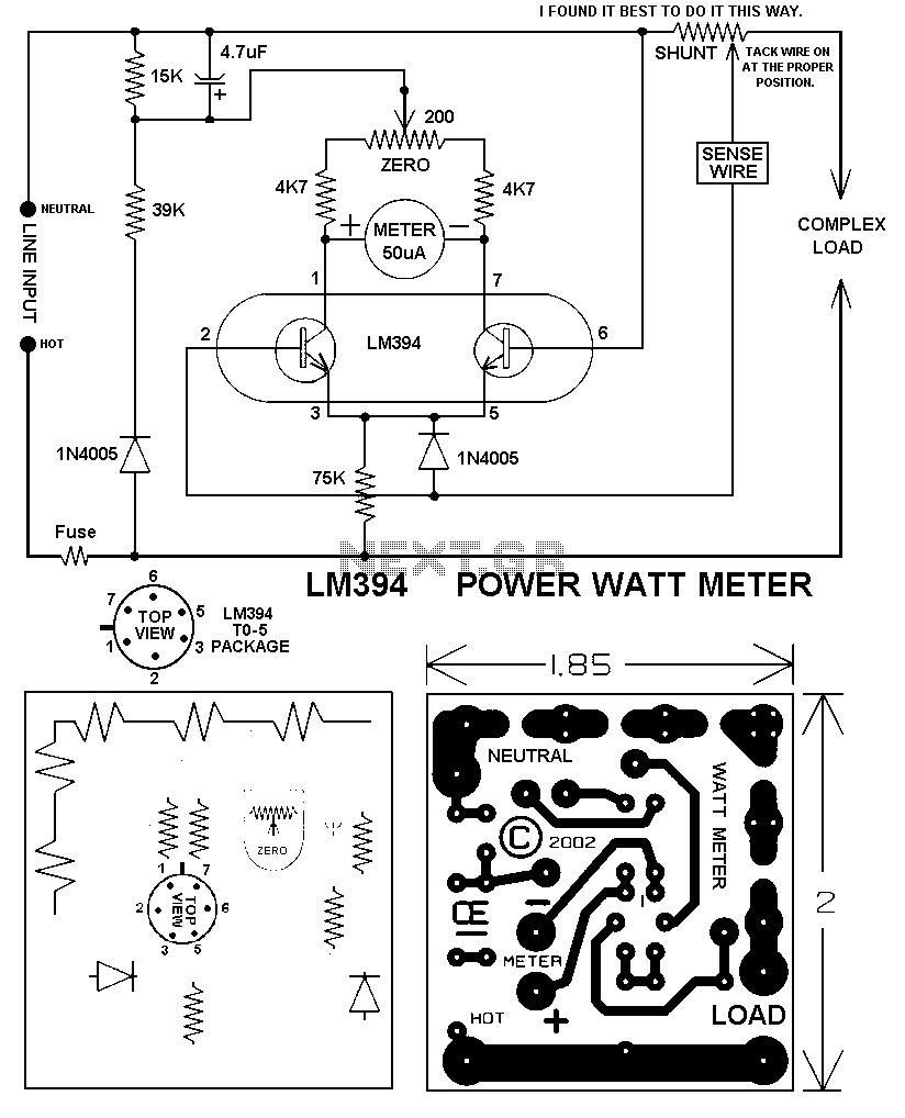
This circuit will give you a good, accurate watt meter that can measure various power levels. In the original article, the shunt was a 0.001 Ohm copper shunt giving a 1000 Watt scale. However, because most circuit breakers in...
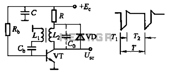
Common non-sinusoidal oscillator circuit, waveform and frequency formula - sawtooth oscillator - use blocking oscillator The sawtooth oscillator is a type of non-sinusoidal oscillator that generates a waveform characterized by a linear rise in voltage followed by a rapid drop....