
doorknob alarm pcb

The alarm circuit described operates on the principle of capacitance sensing, where the presence of a human hand alters the capacitance between the doorknob and the sensing box. The core components of the circuit typically include a capacitance sensor, a microcontroller, and a power supply. The capacitance sensor is usually designed to detect small changes in capacitance, which can be achieved using a simple RC (resistor-capacitor) circuit.
When the metal chain is wrapped around the doorknob, it acts as one plate of a capacitor, while the box containing the electronics serves as the other plate. The circuit continuously monitors the capacitance levels. When a person touches the doorknob from the outside, the capacitance increases due to the additional capacitance introduced by the human body. This change is detected by the microcontroller, which can be programmed to trigger an alarm or send a signal to alert the user.
The use of a low-power microcontroller is crucial for the longevity of the device, allowing it to operate efficiently on minimal energy. Additionally, the circuit can incorporate a sleep mode, where the microcontroller consumes very little power when not actively monitoring the capacitance. When a change is detected, the microcontroller can wake up and activate the alarm system.
Power supply options for this circuit can include standard batteries or even rechargeable lithium-ion cells, depending on the desired form factor and convenience. The design should also include a low battery indicator to alert users when the power supply is running low.
Overall, this circuit design represents a practical and economical solution for personal security, providing a reliable alarm system with minimal power consumption and cost, suitable for various applications in residential and commercial settings.Circuit Many companies offer simple alarm devices for personal use in bedrooms or hotel rooms. A metal chain attached to a box holding the electronics is placed around the inside doorknob of a wood door. Anyone grabbing the knob from the outside is detected by the electrical capacitance change that occurs from the human hand contact between the kn
ob and the box. Almost all of the commercial devices sold use a more expensive and power consuming radio frequency circuit approach to detect the capacitance change. But, a very inexpensive and micro power technique can also work. This circuit schematic should dramatically reduce the cost of the device and allows it to operate for many years from one set of batteries.
🔗 External reference
Related Circuits
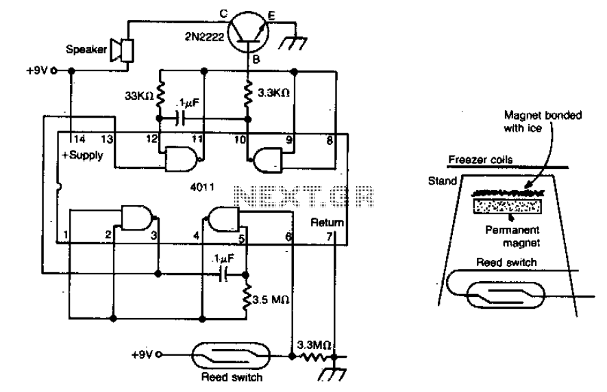
The meltdown consists of a magnet secured to a small stand by ice. A reed switch is positioned beneath the magnet. When the ice melts, the magnet drops onto the switch, closing it and completing the alarm circuit. The described...
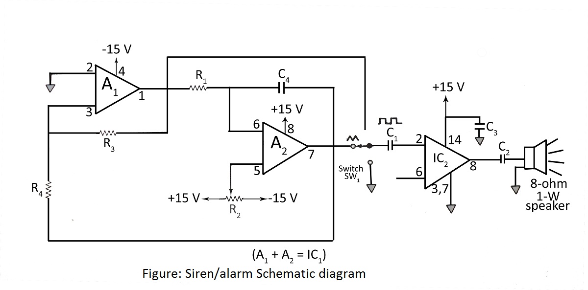
A device such as burglar alarms and sirens, whose basic purpose is to monitor a tested circuit diagram with a description of a burglar alarm using a dual operational amplifier. The burglar alarm system utilizes a dual operational amplifier (op-amp)...
The controller circuit illustrated in Figure 15-24 consists of a switch-type Hall integrated circuit DN838 and an astable multivibrator, which is based on the 555 timer IC. This circuit is suitable for various applications, including automatic door opening, delay...
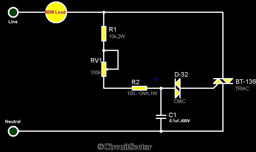
The circuit diagram presented is a triac-diac electronic fan regulator designed to reduce power consumption of electric fans, even at low speeds. Traditional resistor-inductor fan regulators tend to generate excess heat, wasting energy when the fan operates at lower...
This is a circuit diagram for a simple doorbell. The circuit can be assembled indoors, while the switch should be placed outside, making it easily noticeable for visitors. The operation of this circuit is similar to a previous project. The...

The signal begins at a low frequency, increases over approximately 1.15 seconds to a high frequency, pauses for about 0.35 seconds, and then starts to rise again from a low frequency, continuing this pattern indefinitely. The described signal exhibits a...