
Doorknob Proximity Alarm for wooden door

The doorknob alarm circuit operates on the principle of proximity detection using a low-power transmitter and a resonant oscillator. The circuit is designed for non-metallic doors, as the doorknob itself serves as an antenna to transmit a signal. The oscillator generates a radio frequency signal, which is emitted through the doorknob. When a person approaches, their body introduces a capacitive load to the oscillator, causing a shift in the frequency. This frequency shift is detected by the circuit, triggering the alarm.
The core components of the circuit include a transmitter module, a proximity sensor, and an alarm output stage. The transmitter module typically consists of an oscillator circuit, which may be built using a 555 timer IC or a similar oscillator design. The output of this oscillator is connected to the doorknob, allowing it to function as an antenna.
The proximity sensor is designed to detect changes in capacitance caused by the presence of a nearby person. This sensor can be implemented using discrete components or integrated circuits, such as the 74HCT series CMOS logic, which allows for greater flexibility in the design. The CMOS logic can be used to drive various output devices, including sound effect integrated circuits (ICs) or other alarm mechanisms.
When the proximity sensor detects a significant change in the load on the oscillator, it activates the alarm output. This output can be configured to drive a sound-producing device, such as a buzzer or speaker, alerting occupants of the door's proximity to an intruder. The circuit may also include additional features such as adjustable sensitivity, delay timers, or LED indicators to enhance functionality and user experience.
Overall, this reverse-engineered doorknob alarm circuit exemplifies the integration of simple electronic components to create an effective security solution for residential applications.Reverse engineered circuit diagram of a popular retail doorknob alarm. It contains a small transmitter and the doorknob acts as an antenna so it will not work on a metal door. When a person comes close to the doorknob this loads down the oscillator and the alarm sounds. The proximity sensor circuitry is perfectly capable of driving 74HCT series CMOS logic in place of of the sound effect IC`s shown in the circuit diagram.
🔗 External reference
Related Circuits
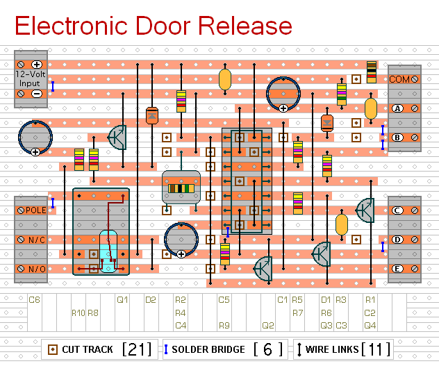
This circuit is designed to operate an electrical door-release mechanism, but it can be adapted for other applications. Upon entering a four-digit code of the user's choice, the relay will energize for a preset duration. The relay contacts can...

This is a fire alarm system utilizing the IC TD2002 suite to detect fire incidents. The alarm is crucial in residential complexes, allowing for early detection. It operates by detecting fog generated by fire, which reduces the light reaching...

The monitor detects an open door, and if the condition is not rectified within 20 seconds, it triggers a beeping alarm. The circuit operates using a magnetic reed switch and a magnet positioned on the door. When the door...
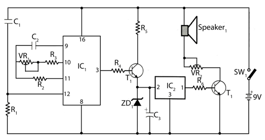
The circuit timer with a musical alarm utilizes a well-known CMOS oscillator/divider integrated circuit (IC1). Although this circuit operates at 9V, its standby current drain is minimal. The time delay of the timer circuit can be adjusted by modifying...

This is a cross-sectional diagram of a flex switch. They can be used as pushbuttons or even position sensors. This schematic diagram shows an oscillator, which is used as an alarm sounder, triggered by a flex switch. The flex switch...
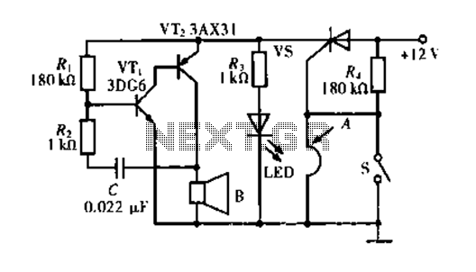
The circuit operates based on a principle where the SCR (Silicon Controlled Rectifier) trigger is grounded, keeping it in the off state. When a burglar triggers the alarm, a voltage is supplied to the SCR trigger, turning it on....