
DUM23-48 300II AC power distribution unit electrical schematic diagram

The OBO V20C lightning protection module is designed to safeguard electrical systems from transient overvoltages caused by lightning strikes. With a maximum lightning damage current rating of 40 kA, this module is suitable for various applications where high levels of surge protection are required.
The module integrates several key components:
- The relay (k) is used for controlling the flow of electrical power based on specific conditions, ensuring that the system can respond effectively to changing electrical states.
- The contactor (KM) serves as a switch that can handle larger currents and voltages, allowing the module to disconnect or connect circuits as needed to prevent damage during a lightning event.
- The fuse (FU) is a critical safety component that protects the circuit by breaking the connection when excessive current flows, thereby preventing potential fires or equipment damage.
- The traffic lights (HL) are utilized for signaling purposes, providing visual indicators for the operational status of the system, which is essential for user awareness and safety.
Incorporating these elements, the OBO V20C not only provides robust lightning protection but also enhances the overall safety and reliability of the electrical installation. Proper integration of this module into a circuit design can significantly reduce the risk of lightning-induced damage, making it an essential component in environments prone to thunderstorms. As shown, OBO V20C as lightning protection module, lightning damage maximum current of 40kA; k relay; KM for the contactor; FU for the fuse; HL traffic lights.
Related Circuits
This circuit can be adapted for other regulated and unregulated voltages by using different regulators and batteries. For a 15 Volt regulated supply use two 12 Volt batteries in series and a 7815 regulator. There is a lot of...
The delay application circuit is depicted in Figure JEC-2, which consists of two components. When the input transitions from logic level 0 to 1, the output also changes to 1 immediately. However, when the input transitions from high level...

This liquid detector circuit diagram is designed using common electronic components. The liquid detector can activate an active buzzer to produce sound when a certain water level is reached. Since the water sensor and control circuit for the buzzer...
This circuit is designed to indicate, via a flashing LED, when room noise exceeds a predetermined threshold, selectable from three fixed levels: 50 dB, 70 dB, and 85 dB. The circuit utilizes two operational amplifiers to amplify the sound...
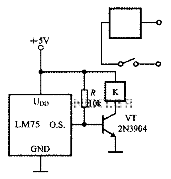
The circuit features simple smart temperature sensors utilizing an I2C bus interface, designed as a thermostat controller circuit. It employs the LM75 temperature sensor connected to a 2N3904 transistor, which drives a relay coil. The relay operates based on...
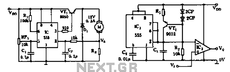
The circuit consists of a 555 motor automatic governor configuration. It includes flip-flops, a 555 timer, and a switching tube. A sampling circuit is formed by connecting R7 and the motor in series. RP1 is used to control the...