
Electric fence charger
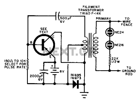
The circuit design described employs a power transistor as a key component, which is responsible for switching the fence wire on and off at a specified pulse rate. The configuration allows for a flexible adjustment of the pulse rate through the base resistor, enabling the user to modify the frequency of operation based on specific requirements.
The choice of a power transistor is critical, as it must be capable of handling the load associated with the fence wire. The transistor's base resistor is calculated using Ohm’s law, considering the desired pulse rate and the characteristics of the transistor being used. A resistor value that produces a pulse rate of around 50 pulses per minute is ideal, but the design accommodates a range from 10 to 100 pulses per minute, allowing for adaptability in various applications.
The fence wire itself must be properly insulated at each pole to prevent electrical leakage and ensure the safety of surrounding animals. The installation height of the wire is also an important factor; it should be positioned low enough to deter animals from attempting to crawl beneath it, which could compromise the effectiveness of the fencing system.
The inclusion of two neon lamps in the circuit serves a dual purpose: they provide a visual indication of the operational status of the unit and enhance user awareness of the system's functionality. When the circuit is active, the neon lamps illuminate, signaling that the fence is operational and providing a clear indication for maintenance or monitoring purposes.
Overall, this circuit design effectively combines the use of a power transistor, adjustable pulse rate control, and visual indicators to create a reliable and functional electric fencing solution. Proper attention to component selection, resistor calibration, and installation practices will ensure optimal performance and safety.Any good power transistor can be used in this circuit. The base resistor should be adjusted to obtain a pulse rate of about 50 pulses per minute. The range of values shown can go from 10 pulses to 100 pulses per minute. The single fence wire must be insulated at each supporting pole and should be mounted low enough to prevent an animal from crawling under the wire. The two neon lamps indicate when the unit is operating. 🔗 External reference
Related Circuits
The Accu charger circuit is straightforward and simple to construct, requiring no more than ten components. In addition to its ease of assembly, this charger circuit is also cost-effective and highly efficient. The circuit requires a power supply from...
A charger is essential for charging a 12 Volt battery from a 12 Volt source due to the typical voltage variation between 11 Volt and 15 Volt. A battery requires a controlled charge current and voltage, which cannot be...
Electrical lines that include lighting circuits originate from the main distribution panel of the installation. Each line consists of three conductors: phase, neutral, and ground. All three conductors extend to the terminal point of each luminaire, and if the...
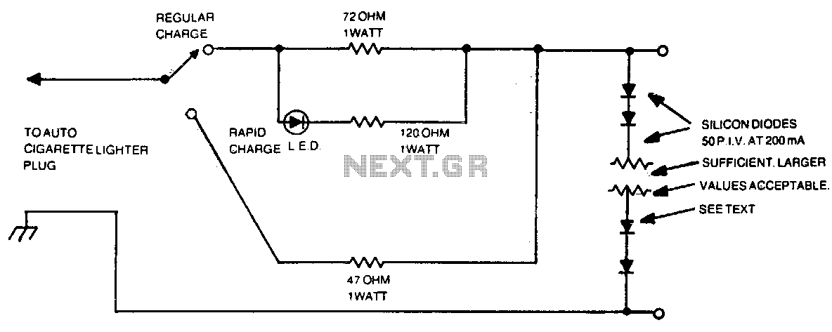
The number of silicon diodes across the output is determined by the voltage of the battery pack. Each diode is considered at 0 volts. For example, a 10-volt pack would require 10/0 = 157, or 16 diodes. In the context...
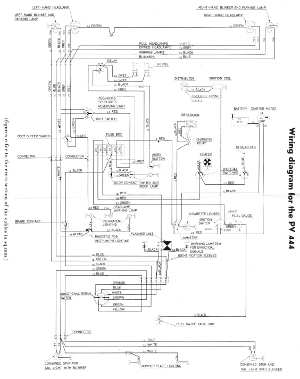
The following circuit illustrates the wiring diagram for the Volvo PV444, a vintage car electrical circuit. It provides an electrical understanding of this uni-body vehicle. The Volvo PV444 wiring diagram serves as a crucial reference for understanding the electrical system...
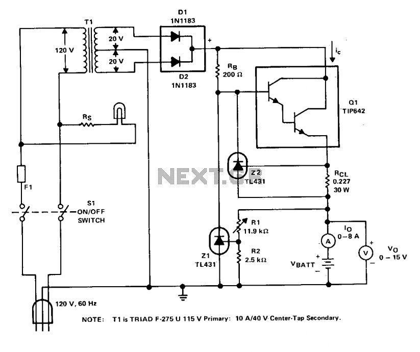
The charger operates with a charging voltage of 2.4 V per cell, aligning with the recommendations of most manufacturers. The circuit delivers a charging voltage of 14.4 V (6 cells at 2.4 V per cell) in a pulsed manner...
Warning: include(partials/cookie-banner.php): Failed to open stream: Permission denied in /var/www/html/nextgr/view-circuit.php on line 713
Warning: include(): Failed opening 'partials/cookie-banner.php' for inclusion (include_path='.:/usr/share/php') in /var/www/html/nextgr/view-circuit.php on line 713