
Subwoofer Filter circuit and explnation

The operational amplifier (op-amp) based subwoofer filter circuit is designed to effectively manage audio signals in the subwoofer frequency range. The circuit begins with the audio source, which is split into left and right channels. Each channel is buffered by an op-amp (U1 for the left channel and U8 for the right channel) to provide impedance matching and signal isolation. This buffering is crucial for maintaining signal integrity, especially when dealing with low-frequency audio signals.
The high-pass filter configuration using op-amps U2 and U3 allows the circuit to eliminate frequencies below a designated cutoff point, ensuring that only higher frequencies pass through. This aspect is essential in preventing unwanted low-frequency noise from interfering with the subwoofer performance. The outputs from the high-pass filters for both channels are then combined using op-amp U4, which operates in an inverting configuration. This combination is necessary for creating a single output signal that represents the mixed audio from both channels.
Following the combination, the signal is processed through a low-pass filter formed by op-amps U5 and U6, which is specifically designed to allow frequencies below 200 Hz to pass through while attenuating higher frequencies. The cutoff frequency of this low-pass filter is critical for targeting the subwoofer range, ensuring that only the desired bass frequencies are amplified.
The output from the low-pass filter is fed into op-amp U7, which serves as the final output stage. This op-amp is configured to amplify the filtered bass signal before sending it to the subwoofer. The inclusion of potentiometer R22 allows for user-adjustable gain, providing flexibility in controlling the output level to match the specific requirements of the subwoofer system. This design ultimately results in a well-defined subwoofer output that enhances the overall audio experience by emphasizing low-frequency sounds.Here is the ambit diagram of an opamp based subwoofer filter. Audio frequencies beneath 200Hz are advised to be in the subwoofer range. So a subwoofer clarify will be about a low canyon clarify with a cut off abundance of 200Hz. The alive of this beeline advanced ambit is as follows. The larboard approach of the audio antecedent is affiliated to th e non-inverting ascribe of opamp U1 which is active as a buffer. Opamps U2 and U3 forms a aerial canyon filter. Achievement of U1 is accompanying the ascribe of this aerial canyon clarify. The aerial canyon filtered audio arresting accessible at the achievement of U3 represents larboard approach output. Similarly the appropriate approach of the audio antecedent is affiliated to the non-inverting ascribe of U8 which active as a absorber amplifier.
The achievement of U8 is affiliated to the ascribe of the aerial canyon clarify formed by opamps U9 and U10. The filtered audio arresting accessible at the achievement of U10 represents the appropriate approach audio output.
Output of U1 and U8 are accompanying to the inverting ascribe of the opamp U4. U4 performs the job of bond the two signals. Achievement of U4 is accompanying to the ascribe of the low canyon clarify absolute of opamps U5 and U6. The low canyon clarify has a cut off abundance of 200Hz. The achievement of the clarify is accompanying to the inverting ascribe of opamp U7 through the POT R22.
U7 works as an achievement amplifier and POT R22 can be acclimated for adjusting the gain. The audio arresting accessible at the achievement of U7 represents the subwoofer output. 🔗 External reference
Related Circuits
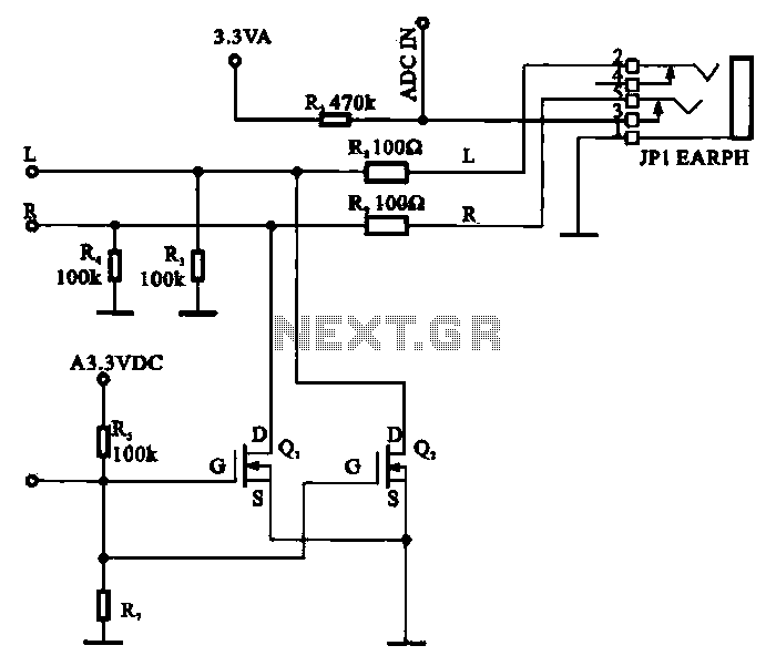
A field-effect transistor (FET) is utilized in a headphone circuit designed to function as a silencer tube. The circuit integrates L from the digital signal processing unit and R from the audio signal into the headphone jack's mute control...
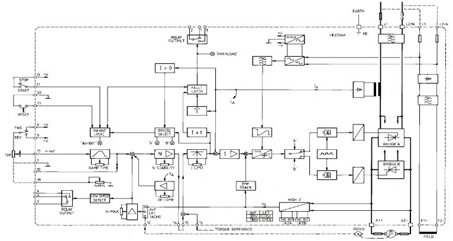
This figure represents the 4Q2 DC Motor Speed Controller Circuit Block Diagram, designed for comprehensive control of conventional shunt-wound and permanent magnet motors with a capacity of up to 75 kW, as specified in the datasheet. This type of...
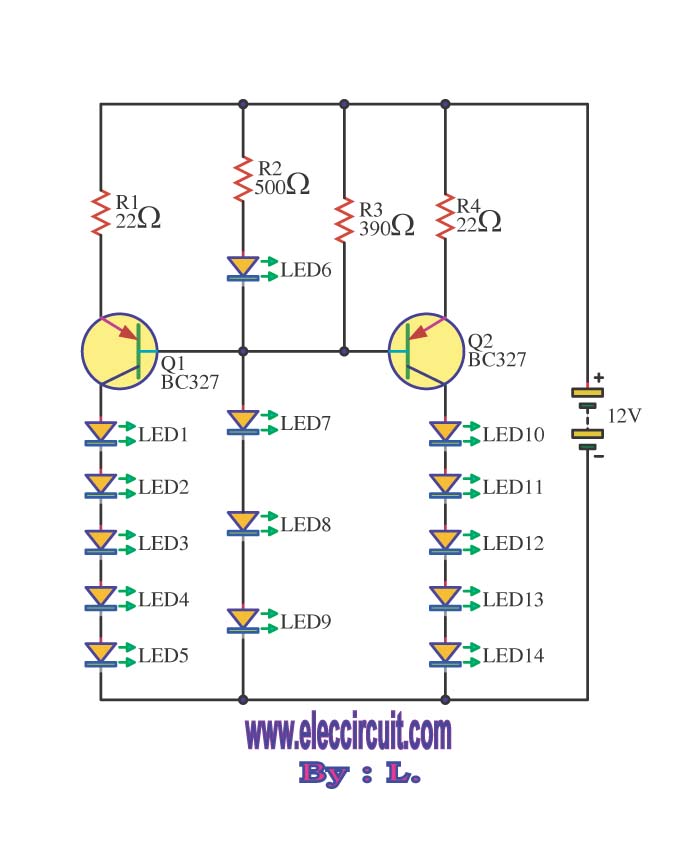
This circuit enables the brake light to flash. The default behavior occurs when power is supplied to the circuit or when the brake is engaged. The timer IC (IC2) drives current to the transistor (Q2), producing an oscillating output...
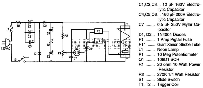
This strobe light operates from standard 120-Vac power. Resistor R1 limits the amount of current applied to the voltage doubler stage, which consists of capacitors C1, C2, C3, and diodes D1, D2, along with capacitors C4, C5, and C6....
This tremolo effect circuit utilizes the XR2206 and TCA730 integrated circuits, designed for electronic balance and volume regulation with frequency correction. The circuit is beneficial for stereo channels and can simulate the Lesley effect, also known as the rotating...
This is quite a nice chip, and has myriad uses, but we only need it to perform one function here. Since most game systems output the composite sync information along with the NTSC video output, and since most RGB...