
Electromagnetic field sensor circuit

The circuit described is a basic electromagnetic field (EMF) sensor designed to detect and amplify the presence of electric fields generated by various sources, including mains transformers and telephone lines. At the core of the circuit is a 1mH inductor, which serves as the sensing element. The inductor's primary function is to respond to the electric field by inducing a small voltage across its terminals, a phenomenon governed by Faraday's law of electromagnetic induction.
The induced voltage is then fed into an operational amplifier (op-amp), which is configured to amplify this signal. The op-amp is a critical component that enhances the weak voltage signal to a level that can be processed further or converted into an audible format. The output of the op-amp is designed to drive a set of headphones, allowing the user to hear the variations in the electric field as sound. For instance, the presence of a 50 Hz hum indicates the proximity to a mains transformer, which is characteristic of alternating current (AC) power systems.
To facilitate user control over the amplification level, a potentiometer (R4) is integrated into the circuit. This component allows for fine-tuning of the gain of the op-amp, enabling the user to adjust the sensitivity of the sensor based on the specific application or environment.
Additionally, the design's versatility is highlighted by its ability to detect signals from telephone lines. When the sensor inductor is positioned near a telephone line, it can pick up the electromagnetic signals associated with voice communication, translating them into audible sounds through the headphones. This feature underscores the circuit's potential applications in both educational and practical settings, such as in electronics troubleshooting or electromagnetic field detection.
Overall, this simple yet effective circuit exemplifies the principles of electromagnetic induction and signal amplification, providing a hands-on tool for exploring the interactions between electric fields and conductive materials.This is a very simple circuit that can be used to sense electromagnetic radiations. The circuit can even detect hidden wrings. A 1mH inductor is used for sensing the electric field. The electric field will induce a small voltage in the sensor inductor and this induced voltage is amplified by the opamp. The headphone connect at the output of the opa mp will give an audio indication of the electric field. For example, the electric field around a mains transformer can be heard as a 50 Hz hum. The POT R4 can be used to adjust the gain of the amplifier. By keeping the sensor inductor near to a telephone line, you can even hear the telephone conversations. 🔗 External reference
Related Circuits
The concept of a color organ involves the transformation of sound, including musical tones, into light. According to wave theory, both music and light possess similar wave characteristics. A color organ is an electronic device that visually represents sound through...
The W7800 is a positive integrated voltage regulator, while the F007 consists of an operational amplifier used in a power supply tracking application circuit. Some configurations utilize both positive and negative power supplies, with a negative supply necessary to...
Joule thief circuit along with videos, circuit diagrams, and explanations. The Joule thief circuit is a minimalist boost converter designed to extract energy from low-voltage sources, such as depleted batteries. This circuit is particularly effective for powering small electronic...
The adjustment potentiometer RP can modify the magnitude of the DC output voltage. The adjustment potentiometer, designated as RP, is an essential component in various electronic circuits, particularly in power supply systems and signal conditioning applications. It serves as a...
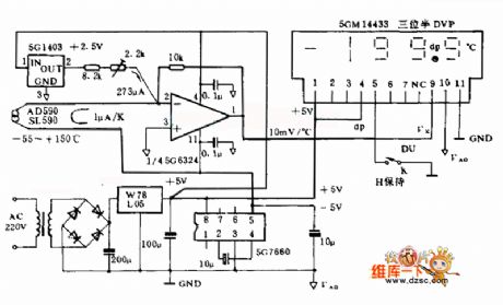
The LM35 temperature sensor provides an output of 10 mV/°C for every degree Celsius over 0°C. At 20°C, the output voltage is 20 x 10 = 200 mV. The circuit consumes 60 µA. The load resistance should not be...
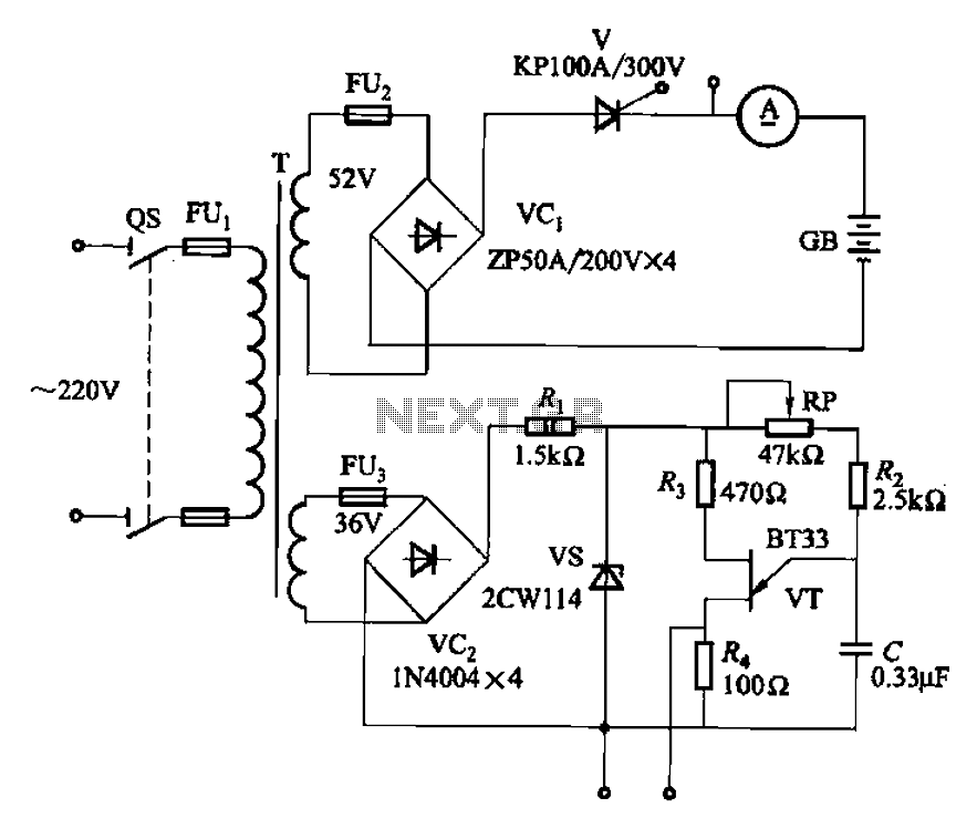
At this voltage regulator prototype the maximum current, with output shortcircuited it was only 0.5 A, so no overheating occurred. In this DC voltage regulator circuit, T1 is for current limitation. As soon as the voltage on the R2...