
Electronic counter

The electronics counter circuit is designed to automate the counting process, minimizing human error during large interval counting. The use of TTL ICs enhances the reliability and speed of the circuit compared to CMOS counterparts, allowing for faster switching and lower propagation delays. The heart of the counting mechanism lies in the interaction between the LDR and the NE555 timer, which serves as a pulse generator.
When an object passes between the light source and the LDR, it interrupts the light beam, causing the LDR's resistance to change. This change triggers the NE555 timer to produce a negative square wave output. The frequency of this output correlates directly with the rate at which objects are counted. The square wave signal is fed into IC2, a binary counter, which counts the pulses generated by the NE555 timer. Each pulse increments the count displayed on the seven-segment displays.
The cascading connection of the counters (IC2 to IC3, IC3 to IC4, IC4 to IC5) allows for counting beyond single digits, enabling the display of numbers up to 10,000 across the four displays. The BCD to 7-segment latch decoder drivers (IC5 and IC6) convert the binary-coded decimal output from the counters into a format suitable for the seven-segment displays, ensuring clear and readable output.
The inclusion of a reset switch (SW1) allows users to easily reset the counter, bringing it back to a known state of 0000. This feature is particularly useful in applications where counting needs to be restarted frequently, providing flexibility and ease of use. Overall, this electronics counter circuit effectively combines various components to create a reliable, user-friendly counting solution suitable for a range of applications.Simple counting can be done by anyone but counting in interval up to large number is tedious and the chance of forget is maximum. As, we have already published Counter Circuit | Digital Counter. Now, here electronics counter is second project by dreamlover technology in the series of counting based project.
Bothe the counting circuit published i n this website counts up to 10, 000 with the help of four seven-segment displays. The difference is previous circuit utilize CMOS ICs where the electronics counter use TTL ICs. The input circuit consists of LDR following by negative square wave generator circuit build around Timer IC (NE555). A bulb is used here as light source focused on LDR. The property of LDR is that whenever the light focused on base of LDR is obstructed, it gives trigger and square wave is generated and given as input signal to counter circuit.
So the objects to be counted are arranged in a row to move one by one in between the light source and the LDR. IC2 shows any number between 0-9 according to input square wave given to pin no 14. After each negative pulse a carrying pulse is produced by decoder IC and given to another one (i. e. from IC2 to IC3, IC3 to IC4, IC4 to IC5 ). IC5 and IC6 is BCD to 7-segment latch decoder driver. The reset switch SW1 is used to reset the electronics counter to 0000 states. 🔗 External reference
Related Circuits
Mechanical contacts have the disadvantage of wearing out. Therefore, it is practical to use an electronic touch switch in certain situations. This type of touch switch utilizes the resistance of human skin for its switching action. The schematic illustrates...
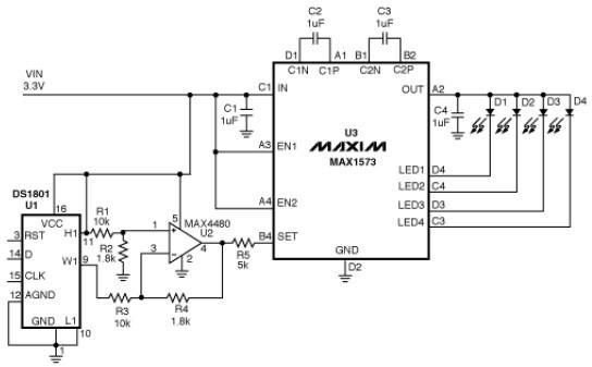
This white LED driver circuit operates up to four white LEDs in parallel from a 3.3V power source, adjusting the total LED current from 1mA to 106mA in 64 steps of 1dB each. The brightness control of the LEDs...
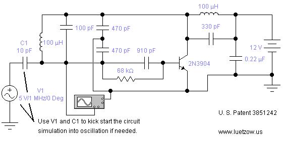
The oscillator circuits presented on this page are derived from expired or non-maintained U.S. Patents. All circuits are formatted for "Electronic Workbench 5.12" or "Multisim 7" circuit simulation software. A note regarding SPICE simulation of electronic oscillator circuits: all...
This review highlights a dual-test scenario involving the FVP preamp, with initial contacts made with Vacuum State and insights provided by Geoff during a trip to Brittany. The FVP was sent to France for evaluation. Geoff tested the FVP5A...
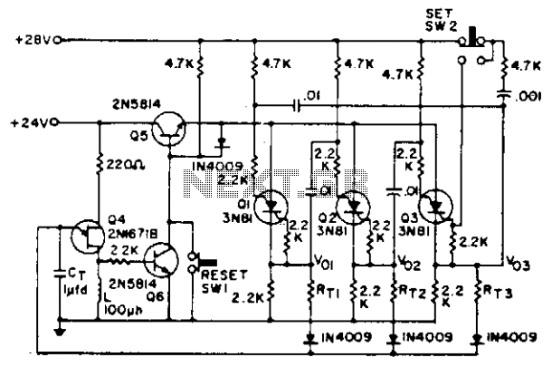
Shift pulses are generated by the unijunction transistors. The intervals between pulses are controlled by CT and RT. A different RT can be selected for each stage of the counter as shown. The circuit utilizes unijunction transistors (UJTs) to generate...
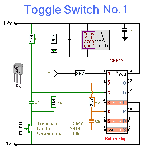
This simple circuit will energize and de-energize a relay with the push of a button. Pressing the button once will energize the relay, while pressing it a second time will de-energize the relay. The accompanying circuit provides a solid...