
ELECTRONIC DICE

The circuit described involves a simple counting mechanism that utilizes a switch (S1), a counter (U2), and an oscillator (U1A/U1B). When the switch S1 is engaged, it triggers the oscillator, which generates a clock signal to drive the counter U2. The counter is capable of counting from 0 to 6, and the current count is visually represented on a display unit labeled DISP1.
The oscillator, comprised of operational amplifiers U1A and U1B, provides a square wave signal that determines the speed at which the counter increments. The frequency of this oscillation is influenced by the values of resistor R1 and capacitor C1, which form an RC timing circuit. The selection of R1 and C1 is critical; they must be chosen to produce a count rate that is fast enough to appear random to the user. This randomness is essential for applications such as gaming or random number generation, where predictable outputs are undesirable.
In practical terms, the values of R1 and C1 can be calculated using the formula for the time period of an RC circuit, which is T = R1 * C1. The frequency (f) of the oscillation can then be derived from the time period (f = 1/T). It is advisable to experiment with different resistor and capacitor values to achieve the desired count rate and ensure that the display updates rapidly enough to give the appearance of randomness.
The output from the counter U2 is connected to the display DISP1, which could be a seven-segment display or an LCD, depending on the design requirements. The display circuitry should be designed to handle the output format from U2 correctly, ensuring that the count is visually represented accurately and clearly.
In summary, this circuit effectively combines a switch, oscillator, counter, and display to create a simple yet functional counting mechanism with a focus on producing a random count output. Proper selection of components is essential to achieve the desired operational characteristics.When S1 is pressed, counter U2 is driven by oscillator U1A/U1B and the count (0 through 6) is read on DISP1. R1 and C1 determine the count rate, which should be fast enough to ensure a "random" count. 🔗 External reference
Related Circuits
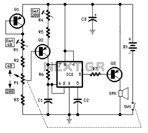
The sound produced imitates the rise and fall of an American police siren. When first switched on, the 10µF capacitor is discharged, and both transistors are off. When the push button switch is pressed, the 10µF capacitor will charge...
An example of an electronic metronome schematic is presented. The electronic metronome is popular due to its simplicity and compact size. The electronic metronome schematic typically consists of several key components that work together to produce a rhythmic sound at...

SI and S2 must be pressed within 200 ms of each other to activate K1. The hold time is adjustable via K7. Additionally, the overlap time of SI and S2 can be modified by changing C1 and C2 or...
This circuit originates from a 14-watt commercial electric spiral bulb from Home Depot. The layout is commendable and credit is due to Sam Goldwasser for its design. The circuit features an interesting oscillator configuration, which will be explained in...
When the output of the multivibrator is low, Q1 (an NPN transistor) will be OFF and Q2 (a PNP transistor) will be ON. Consequently, the negative terminal of capacitor C3 will be connected to ground, allowing it to charge...
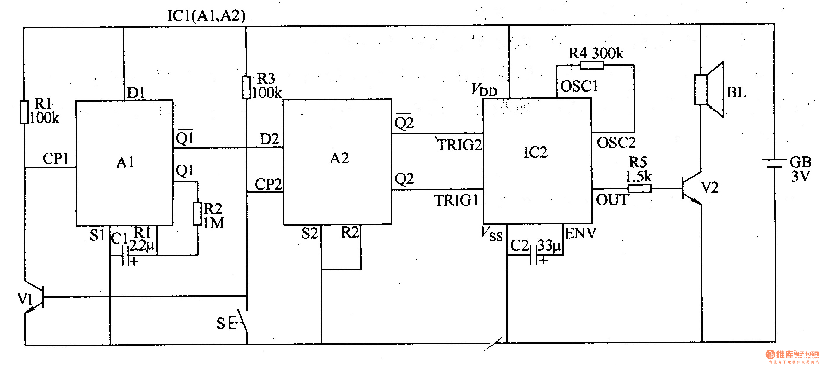
The two-tone electronic doorbell circuit consists of an input trigger circuit and an audio output circuit. The input trigger circuit includes a doorbell button (S), a transistor (V1), resistors (R1-R3), a capacitor (C1), and a dual D flip-flop integrated...