
Telephone Hold Circuit Circuit

The described circuit utilizes a silicon-controlled rectifier (SCR) to control the connection between an LED and a resistor across a telephone line. When the switch SI is engaged, the SCR is triggered into a conductive state. This allows current to flow through LED1 and resistor R1, which are connected in parallel to the telephone line.
The activation of the SCR results in a significant voltage drop across the line, stabilizing at around 20 volts. This voltage level is critical as it ensures that the necessary signaling and communication with the telephone company's central office is maintained. The LED serves as an indicator that the circuit is active, while resistor R1 limits the current to prevent damage to the components.
In practical applications, this configuration can be used in various telecommunication systems where visual indication of line status is required. The use of an SCR allows for efficient control of the circuit, ensuring that the LED lights up only when the switch is pressed, thus providing a clear visual cue while maintaining the integrity of the telephone line connection. Additionally, careful selection of R1 is essential to ensure proper current flow through the LED without exceeding its rated specifications. When SI is pressed, the SCR fires, and places LED1 and Rl across the phone line. The line voltage drops to about 20 V, which holds the connection to the phone company`s central office.
Related Circuits
This circuit addresses the issue of phone line interruptions caused by simultaneous use of a modem or fax machine when another phone is picked up. It indicates the status of the phone line by illuminating a red LED when...
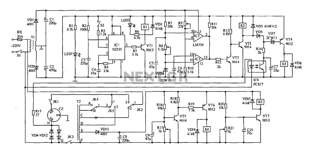
This document presents a power-saving voltage regulator circuit. In addition to its general function as a delay regulator, the circuit features: (1) an automatic voltage regulation capability for mains voltage within a range of 220V ±10%, allowing direct power...
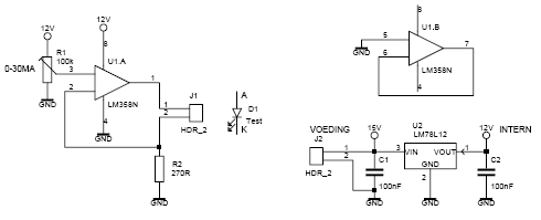
This led tester uses a power switched op-amp. The control range is about 0-30mA. Thus, all test and standard LEDs, the voltage across the LED to read. The power supply is an example lab power supply at least 15V,...
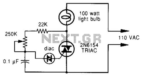
A phase-controlled dimmer delays the triac turn-on to a selected point in each successive AC half cycle. This circuit is suitable only for incandescent lamps, heaters, soldering irons, or universal motors that have brushes. A phase-controlled dimmer is an electronic...
A common issue with small flashlights is the limited lifespan of both the batteries and the bulb. For example, a typical incandescent flashlight consumes approximately 2 Watts, while the LED flashlight shown in Fig. 1 consumes only 24 mW....
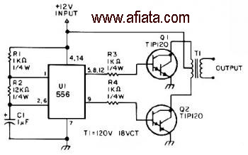
The first section of the 555 timer is configured as an astable oscillator, with R2 and C1 determining the frequency. The output is accessible at pin 5. The second section functions as a phase inverter, with its output available...