
resistance soldering circuitry

The triggering circuitry mentioned serves as a foundational element for various electronic applications, particularly in the realm of signal processing and control systems. Such circuits are essential for initiating actions based on specific input signals, which can be derived from sensors, switches, or other electronic components.
A typical triggering circuit may include components such as transistors, operational amplifiers, and resistors to create a reliable response to input signals. For instance, a simple transistor-based trigger circuit can be designed using an NPN transistor that switches on when a certain voltage threshold is reached. This can be achieved by connecting a resistor to the base of the transistor, which controls the current flow and thus the switching behavior of the circuit.
In more advanced applications, integrating operational amplifiers allows for greater sensitivity and control over the triggering conditions. An op-amp can be configured as a comparator, where it compares the input voltage against a reference voltage. When the input exceeds this reference, the output changes state, effectively triggering the desired action.
In conclusion, while the initial triggering circuitry may not meet all specifications, it lays the groundwork for further development and refinement. By selecting appropriate components and configurations, it is possible to enhance the functionality and reliability of the triggering mechanism to suit specific project requirements.None of this triggering circuitry is quite what you want, but it`ll get you started in the right direction .. 🔗 External reference
Related Circuits
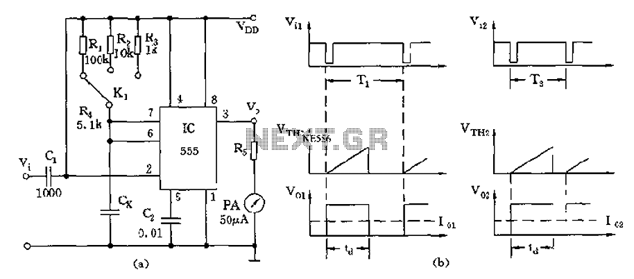
The circuit utilizes a 555 timer along with timing resistors R1 to R3 and a measured capacitance Cx to create a capacitance meter. The principle of capacitance measurement in a one-shot circuit is based on the relationship between the...
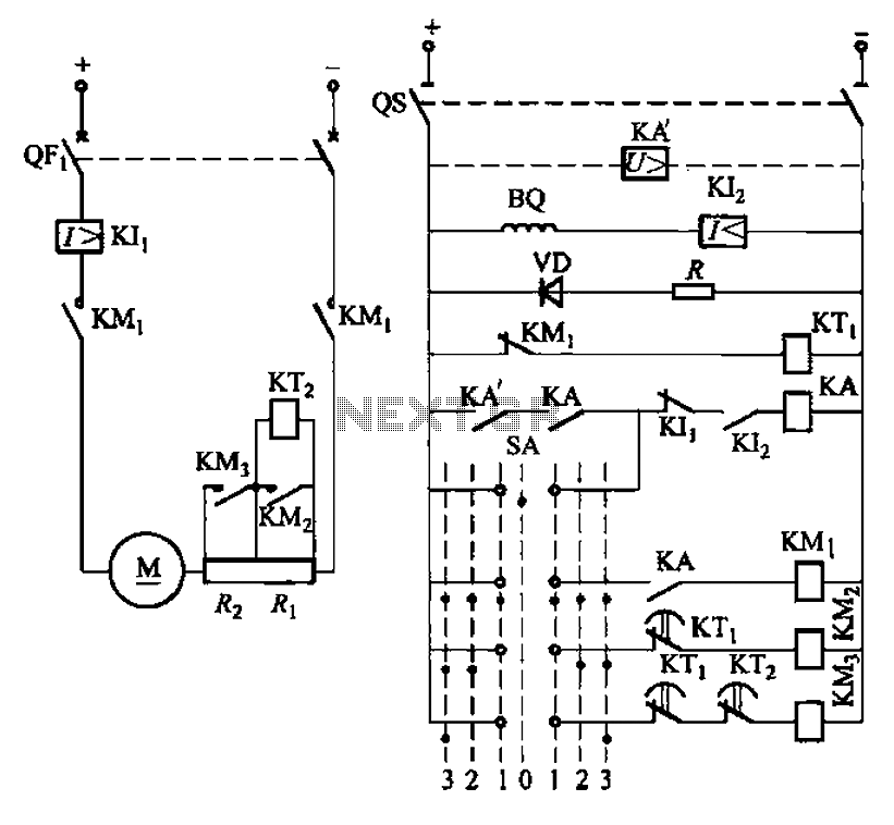
The circuit depicted in Figure 3-190 includes an armature circuit with two startup resistors, Ri and Rz, connected in series through the main switch SA to facilitate starting, stopping, and speed control. During the startup phase, two relays, KTi...
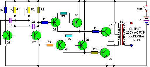
This is a simple and cost-effective inverter designed for small soldering irons (25W, 35W, etc.) to be used in the absence of mains supply. The circuit employs eight transistors along with a few resistors and capacitors. Transistors Q1 and...
A resistance temperature sensor (RTD, resistive temperature device) is available in two types: NTC (negative temperature coefficient) and PTC (positive temperature coefficient). Resistance Temperature Detectors (RTDs) are essential components in temperature measurement systems. They operate on the principle that the...
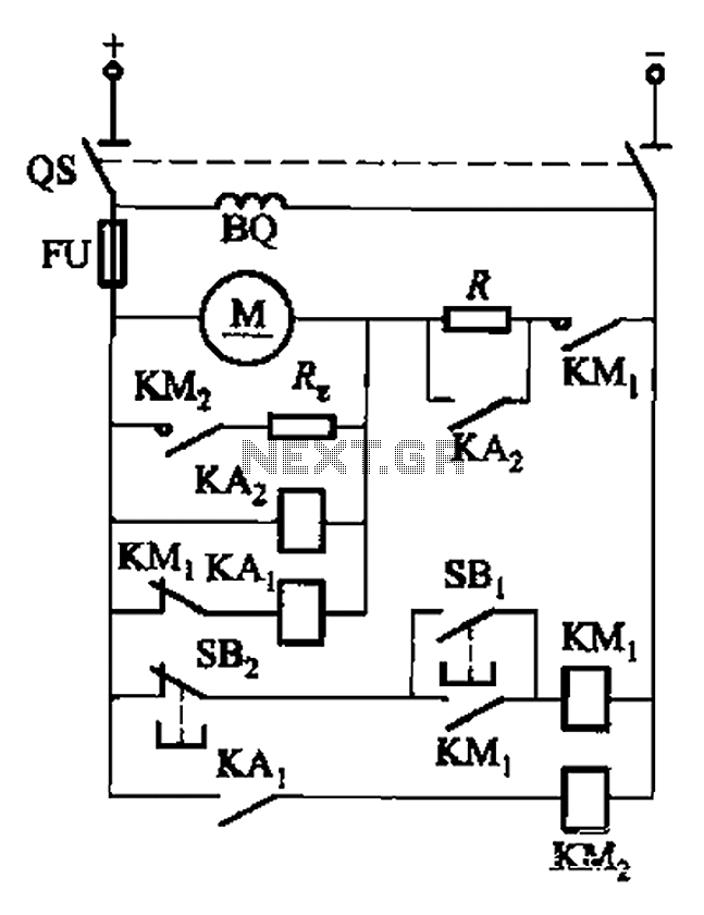
The circuit illustrated in Figure 3-196 features a starting resistance level and an undervoltage relay (KAz) that is controlled by the removal of the startup resistor. It also includes dynamic braking for shutdown purposes. The undervoltage relay (KAL) operates...
This circuit utilizes an LM11 operational amplifier configured as a voltage follower with an input resistance of 1 GΩ, constructed using standard resistor values. When the input is left disconnected, the input offset voltage is amplified by the same...